Regenerative hydraulic systems and methods of use

a hydraulic system and regenerative technology, applied in the field of hydraulic systems, can solve the problems of wasting energy and throttling the flow through the control valve, and achieve the effect of reducing the number of throttlings

Active Publication Date: 2012-09-20
PURDUE RES FOUND INC
View PDF4 Cites 52 Cited by
  • Summary
  • Abstract
  • Description
  • Claims
  • Application Information

AI Technical Summary

Benefits of technology

[0012]According to a second aspect of the invention, a method of using the hydraulic system described above includes installing the system on machinery and moving implements of the machinery with at least the first and second hydraulic actuators. Still other aspects of the invention entail the use of a hydraul

Problems solved by technology

However, throttling flow through con

Method used


Image

  • Regenerative hydraulic systems and methods of use
  • Regenerative hydraulic systems and methods of use
  • Regenerative hydraulic systems and methods of use

Examples


Embodiment Construction

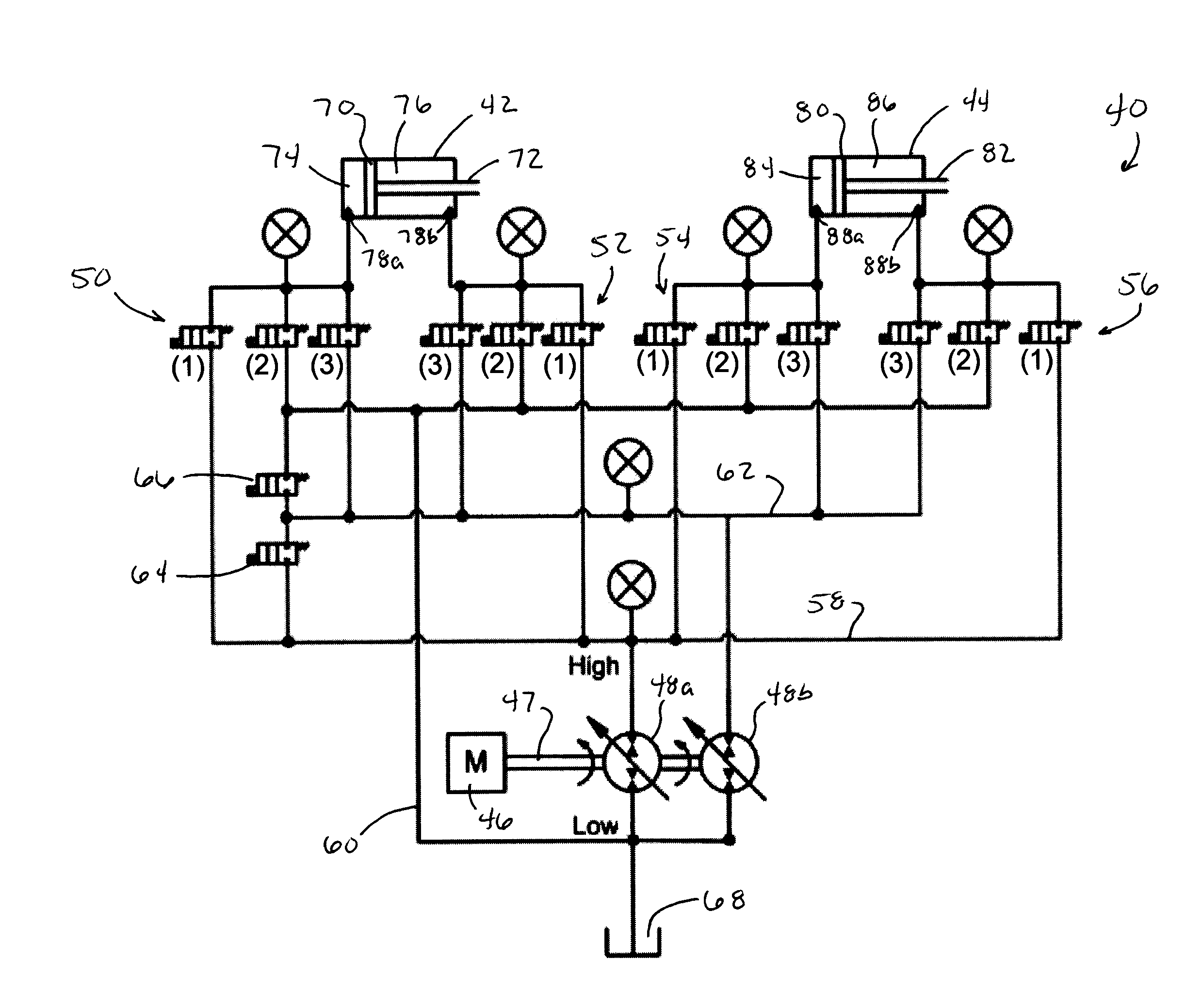
[0022]The present invention provides hydraulic systems capable of controlling the operation of multiple actuators, particular examples of which are linear and rotary actuators. The hydraulic systems contain distributed valve systems and one or more positive displacement units having both pumping and motoring modes. The valve systems and positive displacement units are connected with conduit systems in a manner that enables the hydraulic systems to be operated with enhanced energy efficiency, reliability, and performance.

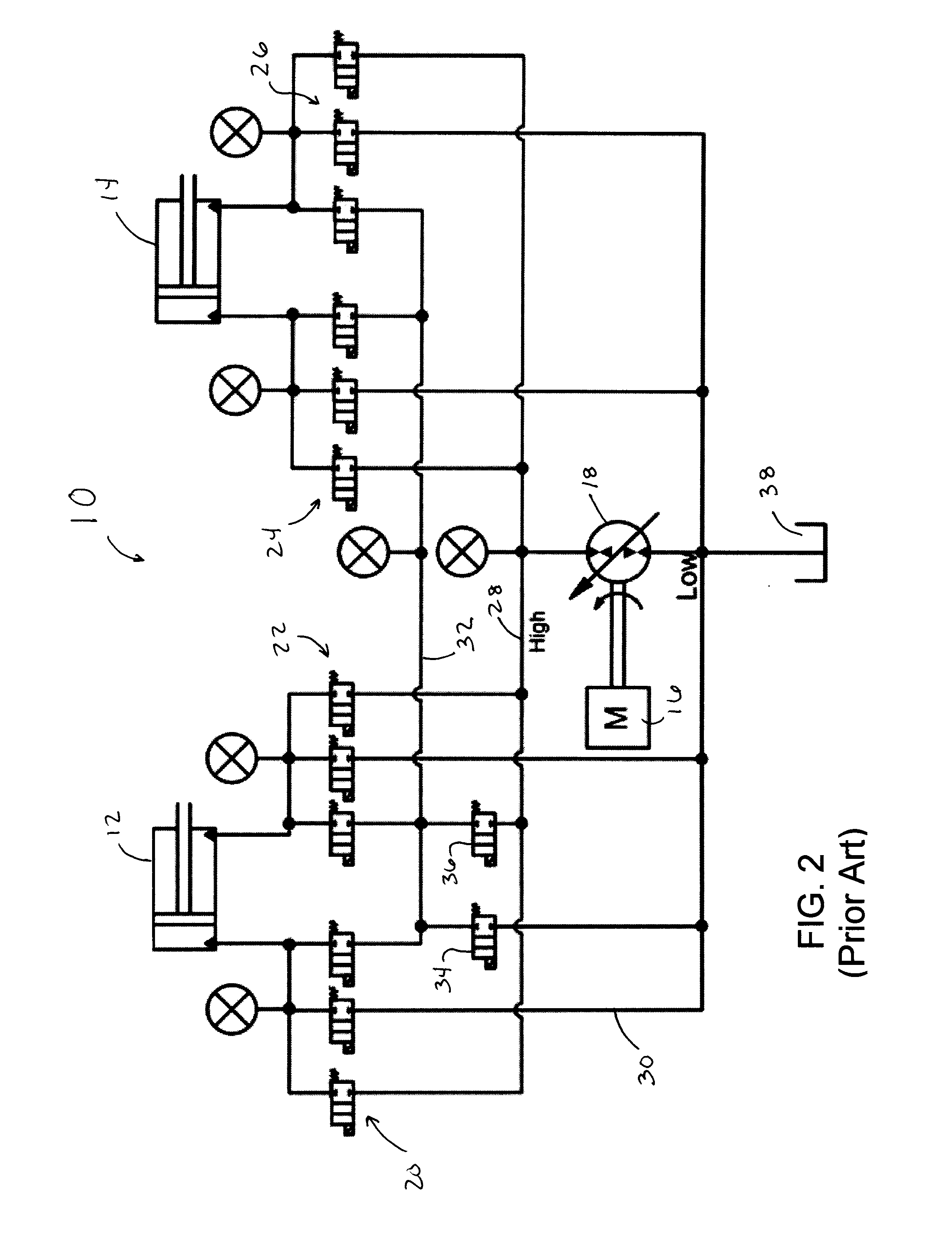
[0023]A hydraulic system 40 according to a first embodiment of the invention is represented in FIG. 3. Similar to the TIER™ system 10 of FIG. 2, the system 40 of FIG. 3 is schematically represented as comprising a pair of hydraulic linear actuators 42 and 44, a prime mover (motor) 46, first and second positive displacement units 48a and 48b, and four sets 50, 52, 54 and 56 of valves. The schematic represented in FIG. 3 is intended to indicate the very basic operating...


PUM


Abstract

Hydraulic systems and methods for using such systems in a variety of machinery, including but not limited to machines having multiple functions performed by one or more hydraulic circuits. The systems enable valves and actuators within the systems to reconfigure themselves so that flow from assistive loads on one or more actuators can be used to move one or more other actuators subjected to a resistive load.

Description

CROSS REFERENCE TO RELATED APPLICATIONS[0001]This application claims the benefit of U.S. Provisional Application No. 61 / 246,551, filed Sep. 29, 2009, the contents of which are incorporated herein by reference.BACKGROUND OF THE INVENTION[0002]The present invention generally relates to hydraulic systems of the types used in machinery, including but not limited to machines having multiple functions performed by one or more hydraulic circuits. More particularly, this invention relates to hydraulic systems that contain one or more positive displacement units capable of operating as pumps and motors, and distributed valve systems that, in combination with the positive displacement unit(s), can be used to control multiple actuators of multi-function machinery.[0003]Compact excavators, wheel loaders and skid-steer loaders are examples of multi-function machines whose operations involve controlling movements of various implements of the machines. FIG. 1 illustrates a compact excavator 100 as...

Claims


Application Information

Patent Timeline
IPC IPC(8): F15B13/02F15B11/20
CPCE02F9/2217F15B2211/88E02F9/2239F15B11/17F15B2211/20561F15B2211/20576F15B2211/214F15B2211/30565F15B2211/30595F15B2211/3138F15B2211/31547F15B2211/41545F15B2211/71F15B2211/761E02F9/2221
Inventor ANDRUCH, III, JOHNLUMKES, JR., JOHN H.
Owner PURDUE RES FOUND INC
Why Eureka
Try Eureka