Power transmission apparatus for hybrid vehicle

Active Publication Date: 2012-09-20
SUBARU CORP
View PDF5 Cites 14 Cited by
  • Summary
  • Abstract
  • Description
  • Claims
  • Application Information

AI Technical Summary

Benefits of technology

[0011]An object of the present invention is to improve a power transmission efficiency of a hybrid vehicle.
[0014]In the power transmission apparatus according to the present invention, a plurality of torque transmission paths are formed between the engine output shaft and motor output shaft and the drive wheel by the two one-way clutches disposed on the respective end portions of the motor output shaft, and therefore the torque transmission path can be switched without using a hydraulic clutch. As a result, the need to activate an oil pump to switch the torque transmission path is eliminated, making it unnecessary to use an electric oil pump to switch the torque transmission path when the engine is stopped.
[0015]The motor output shaft of the electric motor is directly coupled to the output transmission shaft, and therefore the motor output can be transmitted to the drive wheel without activating the shift mechanism. When the shift mechanism is not activated, there is no need to supply oil pressure to the shift mechanism, and therefore power transmission loss can be eliminated. When recovering the regenerative braking energy, the torque from the drive wheel can be transmitted directly to the electric motor without passing through the shift mechanism, and therefore regenerative energy can be recovered efficiently without power transmission loss.

Problems solved by technology

In the conventional hybrid vehicles described above, the engine output and the motor output are transmitted to the drive wheel via a shift mechanism, and therefore power transmission loss in the shift mechanism is inevitable.
When the electric motor is caused to serve as a generator order to recover regenerative energy, regenerative torque from the drive wheel is transmitted to the electric motor via the shift mechanism, leading to further power transmission loss.
Hence, in a power transmission apparatus for a hybrid vehicle employing a shift mechanism, a hydraulic pump for driving the shift mechanism must be driven, and therefore, in addition to the power transmission loss occurring the shift mechanism, power loss inevitably occurs when driving the hydraulic pump.

Method used


Image

  • Power transmission apparatus for hybrid vehicle
  • Power transmission apparatus for hybrid vehicle
  • Power transmission apparatus for hybrid vehicle

Examples


Embodiment Construction

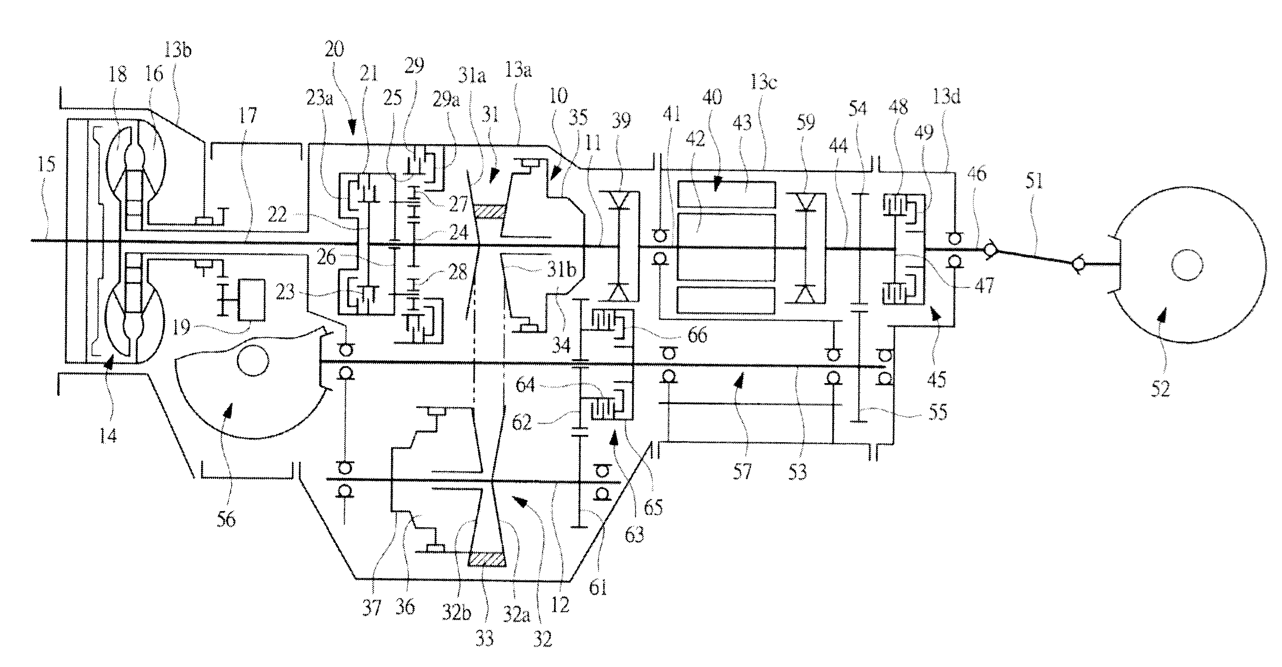
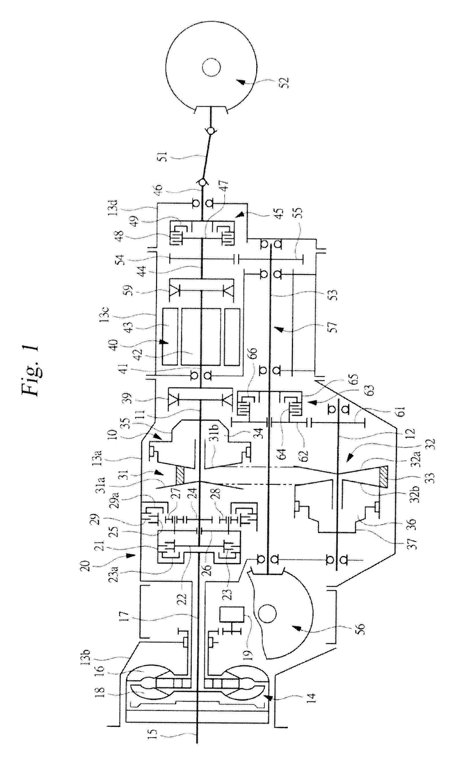
[0021]An embodiment of the present invention will be described below in detail on the basis of the drawings. A power transmission apparatus shown in FIG. 1 includes a continuously variable transmission 10 serving as a shift mechanism. The continuously variable transmission 10 includes a primary shaft 11 serving as a transmission input shaft and a secondary shaft 12 serving as a transmission output shaft. The primary shaft 11 and the secondary shaft 12 are parallel to each other. The continuously variable transmission 10 is incorporated into a transmission case 13a, and the transmission case 13a is installed vertically in an unillustrated vehicle body so that the primary shaft 11 and the secondary shaft 12 are each parallel to a travel direction.

[0022]A torque converter 14 is incorporated into a converter case 13b attached to a tip end portion of the transmission case 13a. The torque converter 14 includes a pump impeller 16 coupled to a crankshaft of an unillustrated engine or in oth...


PUM


Abstract

A power transmission apparatus includes a first one-way clutch disposed between a motor output shaft of an electric motor and a primary shaft, and a second one-way clutch disposed between an output transmission shaft coupled to a drive wheel and the motor output shaft. Using the motor output shaft as a reference, the two one-way clutches transmit torque in a single direction and do not transmit torque in the opposite direction. The one-way clutches are not operated using oil pressure, while power is not transmitted in a single direction in accordance with a torque magnitude. Therefore, a plurality of torque transmission paths are formed in the power transmission apparatus without the need for an oil pressure supply.

Description

CROSS-REFERENCE TO RELATED APPLICATIONS[0001]The present application claims priority from Japanese Patent Application No. 2011-058906, filed on Mar. 17, 2011, the entire contents of which are hereby incorporated by reference.BACKGROUND OF THE INVENTION[0002]1. Field of the Invention[0003]The present invention relates to a power transmission apparatus for a hybrid vehicle in which an engine output and a motor output are transmitted to a drive wheel.[0004]2. Description of the Related Art[0005]In a hybrid vehicle that is installed with an engine and an electric motor so that an engine output and a motor output can be transmitted to a drive wheel, the engine output is transmitted to the drive wheel via a shift mechanism. In a hybrid vehicle installed with a shift mechanism, the engine and the electric motor may be arranged such that the engine is disposed on one end portion side of a transmission input shaft of the shift mechanism and the electric motor is disposed on the other end por...

Claims


Application Information

Patent Timeline
IPC IPC(8): F16H37/06B60L50/16
CPCB60K6/383B60K6/48B60K6/543B60K2006/4825Y02T10/6252Y10T74/19126Y10T74/19019Y10T74/19144Y10T74/19014Y10T74/19051Y02T10/6221Y02T10/62
Inventor OKI, SHOGO
Owner SUBARU CORP
Why Eureka
Try Eureka