Co2 recovery apparatus
a recovery apparatus and co2 technology, applied in the direction of chemistry apparatus and processes, separation processes, dispersed particle separation, etc., can solve the problem of large heat energy consumption, and achieve the effect of reducing the amount of water vapor to be supplied to the regenerative superheater
- Summary
- Abstract
- Description
- Claims
- Application Information
AI Technical Summary
Benefits of technology
Problems solved by technology
Method used
Image
Examples
first embodiment
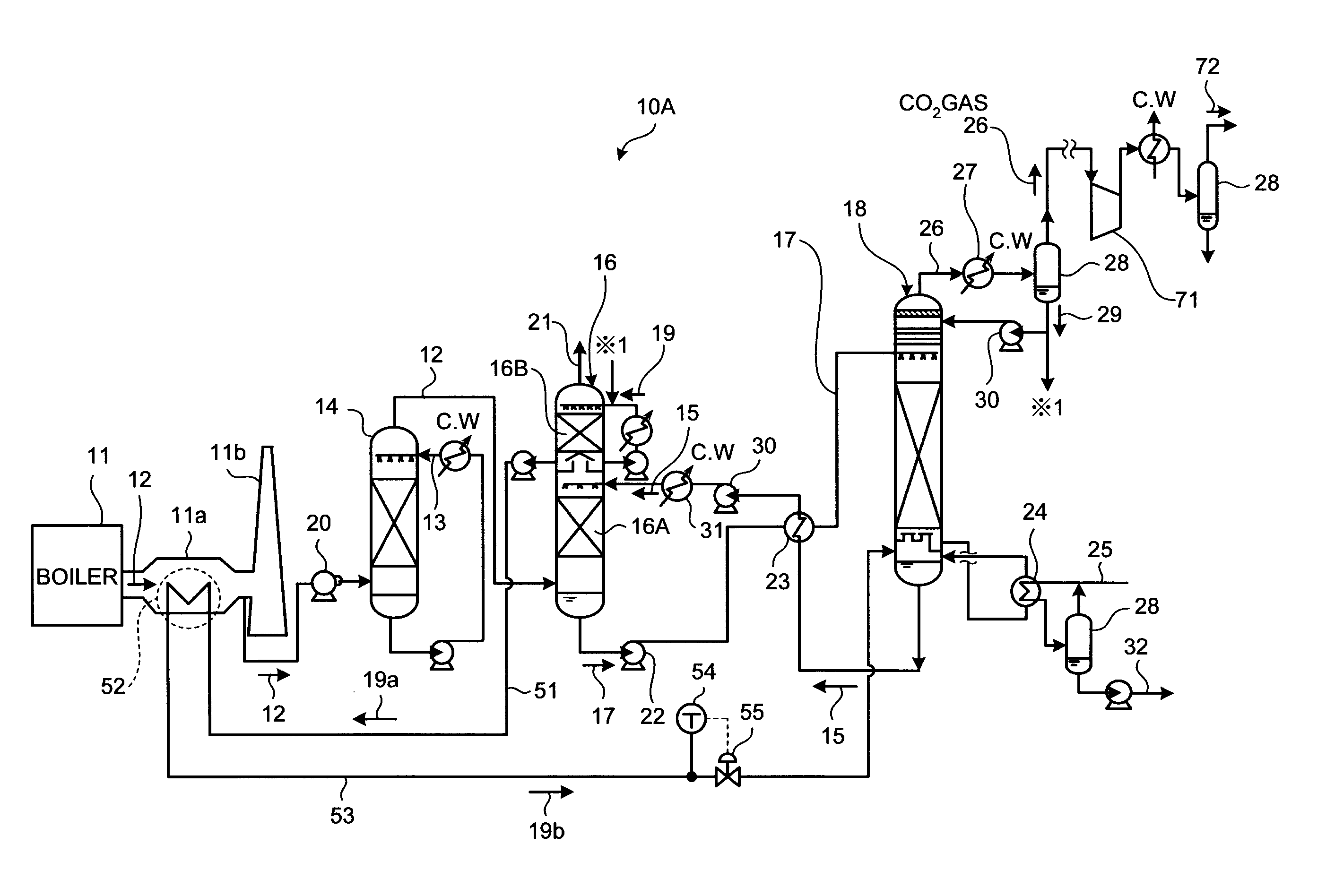
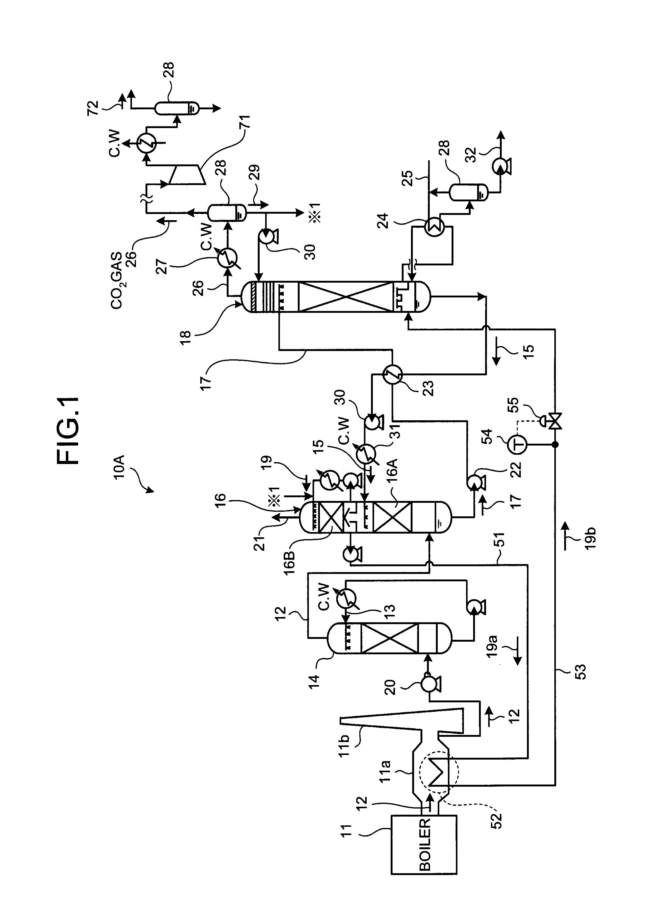
[0024]A description will now be made to a CO2 recovery apparatus according to an embodiment of the present invention with reference to FIG. 1.
[0025]FIG. 1 is a schematic view illustrating the configuration of a CO2 recovery apparatus according to a first embodiment. As shown in FIG. 1, a CO2 recovery apparatus 10A according to the first embodiment includes a flue gas cooling apparatus 14, a CO2 absorber 16, and an absorbent regenerator 18. The flue gas cooling apparatus 14 uses cooling water 13 to cool flue gas 12 containing CO2 and O2 that are emitted from an industrial combustion facility 11, such as a boiler or gas turbine. The CO2 absorber 16 includes a CO2 recovery section 16A for bringing the cooled CO2 containing flue gas 12 and a CO2-absorbing CO2 absorbent (hereinafter also referred to as the “absorbent”) 15 into contact with each other to reduce CO2 in the flue gas 12. The absorbent regenerator 18 causes CO2 to be released from the CO2-absorbed CO2 absorbent (hereinafter a...
second embodiment
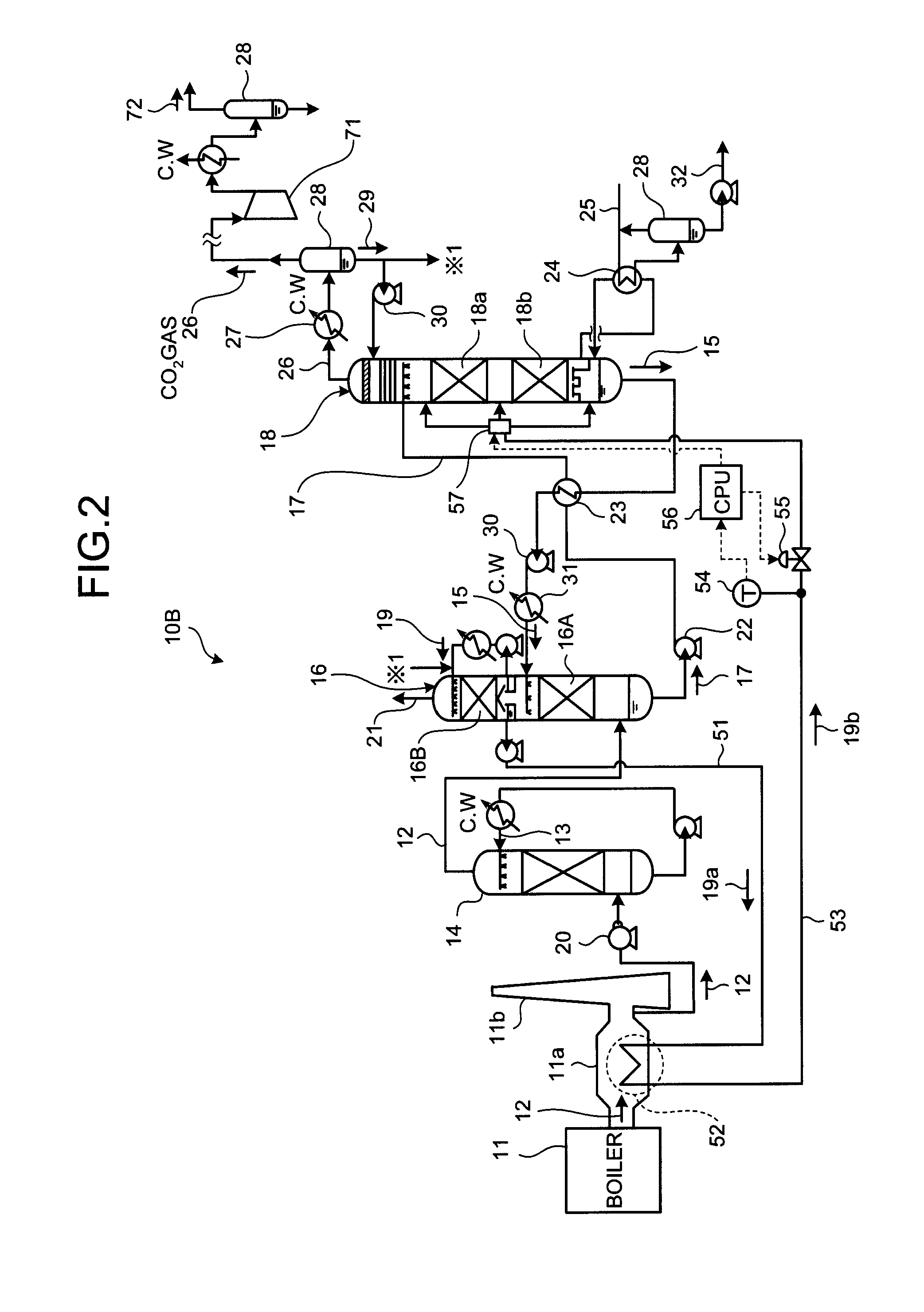
[0043]Now, a description will be made to a CO2 recovery apparatus according to an embodiment of the present invention with reference to FIG. 2. Note that the same members as those of the first embodiment will be denoted with the identical symbols without describing them repeatedly.
[0044]FIG. 2 is a schematic view illustrating the configuration of a CO2 recovery apparatus according to a second embodiment. As shown in FIG. 2, a CO2 recovery apparatus 10B according to the second embodiment is different from the CO2 recovery apparatus 10A of the first embodiment in that the destination of the superheated cleansing water 19b can be changed.
[0045]In the first embodiment, the superheated cleansing water 19b is supplied to the bottom portion of the absorbent regenerator 18. However, when the superheated cleansing water is at a low temperature, supplying to the bottom portion will cause the lean solution, with which heat was exchanged in the regenerative superheater 24, to have a lowered ste...
third embodiment
[0049]Now, a description will be made to a CO2 recovery apparatus according to an embodiment of the present invention with reference to FIG. 3. Note that the same members as those of the first embodiment will be denoted with the identical symbols without describing them repeatedly.
[0050]FIG. 3 is a schematic view illustrating the configuration of a CO2 recovery apparatus according to a third embodiment. Here, FIG. 3 shows part of the whole system of FIG. 1 or the main portions such as the absorber and the regenerator with the other components being identical to those of the first embodiment.
[0051]As shown in FIG. 3, a CO2 recovery apparatus 10C according to the third embodiment is different from the CO2 recovery apparatus 10A of the first embodiment in that the interior of the absorbent regenerator 18 is divided into three portions including a first stage portion 18a, a second stage portion 18b, and a third stage portion 18c.
[0052]Then, the semi-lean solution 15a diverted from each...
PUM
| Property | Measurement | Unit |
|---|---|---|
| temperature | aaaaa | aaaaa |
| temperature | aaaaa | aaaaa |
| temperatures | aaaaa | aaaaa |
Abstract
Description
Claims
Application Information
 - R&D
- Intellectual Property
- Life Sciences
- Materials
- Tech Scout
- Unparalleled Data Quality
- Higher Quality Content
- 60% Fewer Hallucinations
Browse by: Latest US Patents, China's latest patents, Technical Efficacy Thesaurus, Application Domain, Technology Topic, Popular Technical Reports.
© 2025 PatSnap. All rights reserved.Legal|Privacy policy|Modern Slavery Act Transparency Statement|Sitemap|About US| Contact US: help@patsnap.com


