
Damping device

a technology of damping force and generating member, which is applied in the direction of shock absorbers, liquid based dampers, vibration dampers, etc., can solve the problems of the inability to realize the desired characteristic, etc., and achieves the effect of increasing the flow resistance and increasing the passage resistance of the orifi

Active Publication Date: 2012-09-20
KYB CORP
View PDF4 Cites 23 Cited by
  • Summary
  • Abstract
  • Description
  • Claims
  • Application Information

AI Technical Summary

Benefits of technology

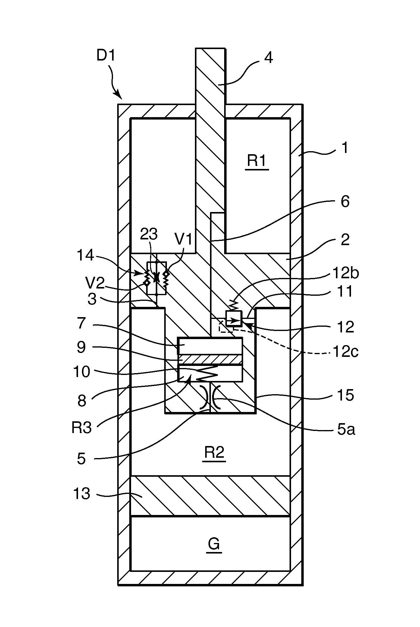
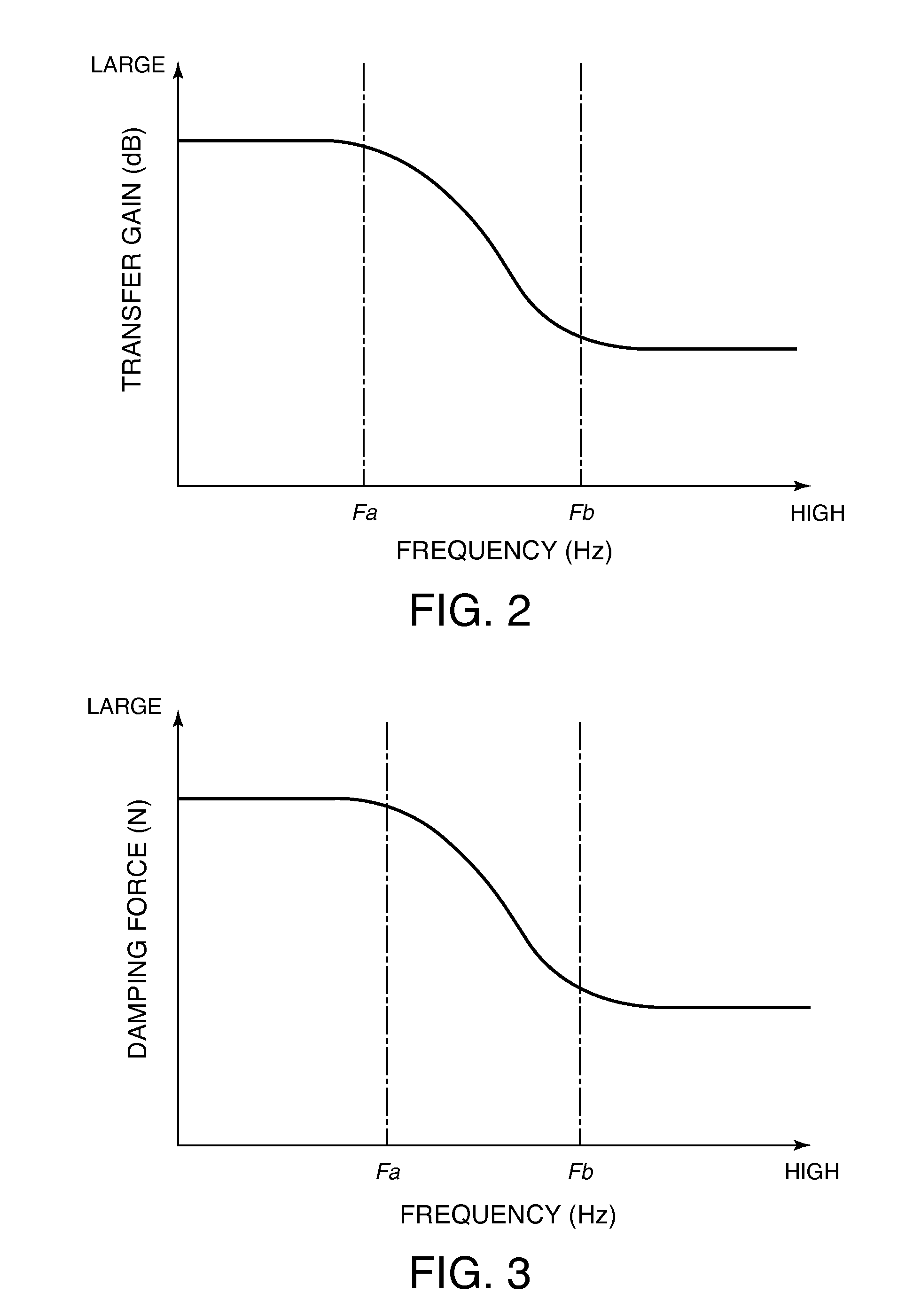
[0019]To generate a large damping force in response to low frequency vibration and a small damping force in response to high frequency vibration, an orifice is provided in the second passage of the damping device according to the prior art. The orifice has a flow rate characteristic according to which an increase in the flow rate leads to a dramatic increase in flow resistance. It may therefore be impossible to realize the desired characteristic whereby a small damping force is generated in response to high frequency vibration when, for example, the vehicle travels over an irregularity on the road surface such that the piston displaces at an extremely high speed, causing a passage resistance of the orifice to increase greatly beyond a passage resistance of the first passage.
[0020]It is therefore an object of this invention to provide a damping device in which an increase in a damping force generated when a piston operates at a high speed can be suppressed, regardless of a frequency of vibration input into the piston.

Problems solved by technology

It may therefore be impossible to realize the desired characteristic whereby a small damping force is generated in response to high frequency vibration when, for example, the vehicle travels over an irregularity on the road surface such that the piston displaces at an extremely high speed, causing a passage resistance of the orifice to increase greatly beyond a passage resistance of the first passage.

Method used


Image

  • Damping device
  • Damping device
  • Damping device

Examples


second embodiment

[0122]Referring to FIG. 7, this invention will be described.

[0123]A damping device D2 according to this embodiment differs from the first embodiment shown in FIG. 1 in that two relief valves 12 and 17 are provided between the connecting passage 6 and the lower chamber R2 in accordance with a flow direction. Accordingly, the damping device D2 comprises a bypass passage 16 provided in parallel with the bypass passage 11 to connect the connecting passage 6 to the lower chamber R2, and the relief valve 17 is provided in the bypass passage 16. The bypass passage 11 and the relief valve 12 are configured similarly to those of the first embodiment, shown in FIG. 1.

[0124]The relief valve 17 opens the bypass passage 16 when the pressure in the lower chamber R2 exceeds the pressure in the connecting passage 6 such that the differential pressure therebetween reaches a relief pressure. As a result, the working oil in the lower chamber R2 flows into the upper chamber R1 through the connecting pa...

third embodiment

[0164]Referring to FIG. 15, this invention will be described.

[0165]A damping device D3 shown in the figure varies the characteristic of the generated damping force relative to the piston speed during both the expansion stroke and the contraction stroke of the piston 2 using the single relief valve 12. Accordingly, the relief valve 12 used in the damping device D3 is configured differently to that of the damping device D11 shown in FIG. 6.

[0166]More specifically, in the damping device D3, the relief valve 12 is constituted by a single flattened ring-shaped leaf, a center of which is penetrated by the small diameter portion 4a of the piston rod 4. The relief valve 12 may be constituted by laminated leaves. An outer periphery of the relief valve 12 is seated on an annular valve seat 40a provided on the valve disc 40, and an inner periphery of the relief valve 12 is seated on the upper end 34b, in the figure, of the inner tube 34. The bypass passage 11 is formed in the valve disc 42, an...

fourth embodiment

[0172]Referring to FIGS. 16 and 17, this invention will be described.

[0173]Damping devices D41 and D42 according to this embodiment differ from the second embodiment in that the bypass passages 11 and 16 connect the upper chamber R1 to the lower chamber R2 via the upper pressure chamber 7.

[0174]In the damping device D41 shown in FIG. 16, the valve case 41 of the relief valve unit 2B comprises a tubular body 77 fitted respectively to the outer periphery of the valve disc 42 and an outer periphery of the upper end 34b of the inner tube 34 in the pressure chamber unit 2C. A seal ring 76 is interposed between the tubular body 77 and the outer periphery of the valve disc 42. The seal ring 76 prevents leakage of the working oil between the space 45 and the lower chamber R2 and absorbs radial direction backlash between the tubular body 77 and the valve disc 42.

[0175]The plurality of inclined holes 42a and 42b are formed in the valve disc 42, similarly to the damping device D21 shown in FIG...


PUM


Abstract

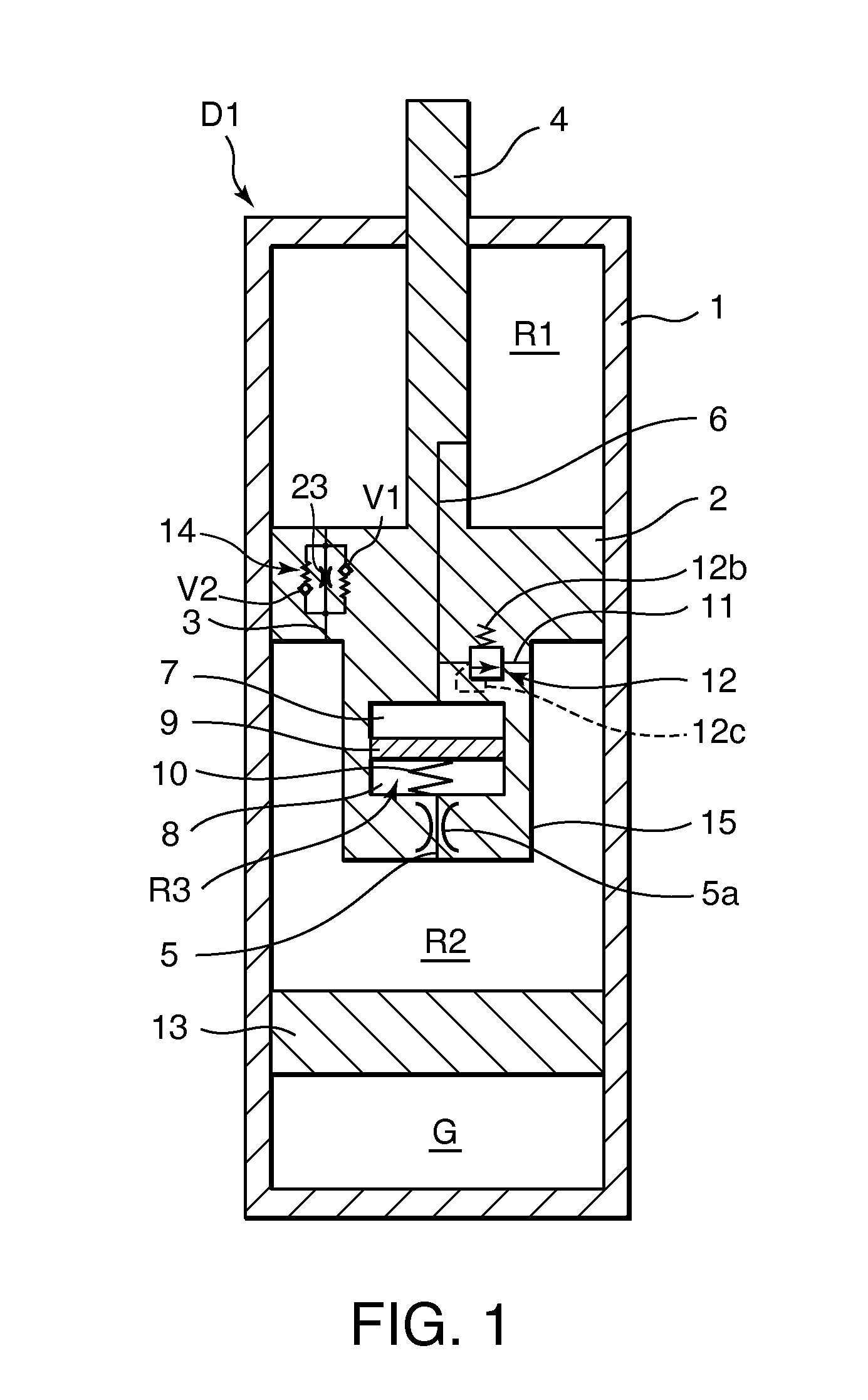
A damping device comprises a piston that partitions an interior of a cylinder into first and second working chambers. A flow-rate-dependent damping force generating element connects the first and second working chambers. A first pressure chamber and a second pressure chamber divided by a free piston are formed integrally with the piston. A first connecting passage connects the first working chamber and the first pressure chamber, and a second connecting passage connects the second working chamber and the second pressure chamber. By providing a relief valve that allows fluid to flow from the first working chamber into the second working chamber, an increase in the generated damping force during a high speed operation of the piston can be suppressed, regardless of a vibration frequency of the piston.

Description

FIELD OF THE INVENTION[0001]This invention relates to an arrangement of a damping force generating member of a damping device.BACKGROUND OF THE INVENTION[0002]JP2006-336816A and JP2007-078004A, published by the Japan Patent Office in 2006 and 2007, respectively, disclose a damping device comprising an upper chamber and a lower chamber defined as working chambers by a piston housed in a cylinder, a first passage that penetrates the piston in order to connect the upper chamber and the lower chamber under a predetermined flow resistance, a pressure chamber formed in the piston, a free piston that partitions the pressure chamber into an upper pressure chamber that communicates with the upper chamber and a lower pressure chamber that communicates with the lower chamber, and a coil spring that supports the free piston elastically.[0003]The pressure chamber does not connect the upper chamber and the lower chamber directly, but when the free piston displaces, a volume ratio between the uppe...

Claims


Application Information

Patent Timeline
Patent Type & Authority Applications(United States)
IPC IPC(8): F16F9/50F16F9/34F16F9/19
CPCF16F9/5126F16F9/348F16F9/32F16F9/34F16F9/50
Inventor TERAOKA, TAKASHIINAMITSU, KAZUTAKA
Owner KYB CORP
Learn More