
Regenerable Filter Unit, Regenerable Filter System Including The Same, And Method Of Operating Regenerable Filter System

a filter system and regenerable technology, applied in water treatment multi-stage treatment, membranes, separation processes, etc., can solve the problems of increased costs and inconvenience for users, arsenic (as) which may present a fatal level of toxic to humans, and the inability to completely remove by-products, so as to reduce the maintenance cost for users

Active Publication Date: 2012-09-20
SAMSUNG ELECTRONICS CO LTD
View PDF5 Cites 10 Cited by
  • Summary
  • Abstract
  • Description
  • Claims
  • Application Information

AI Technical Summary

Benefits of technology

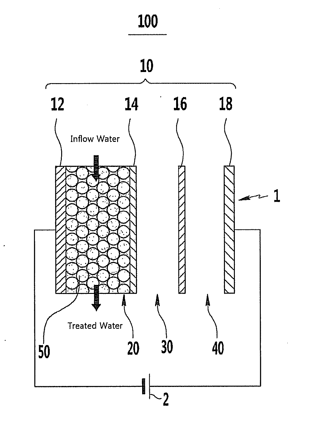
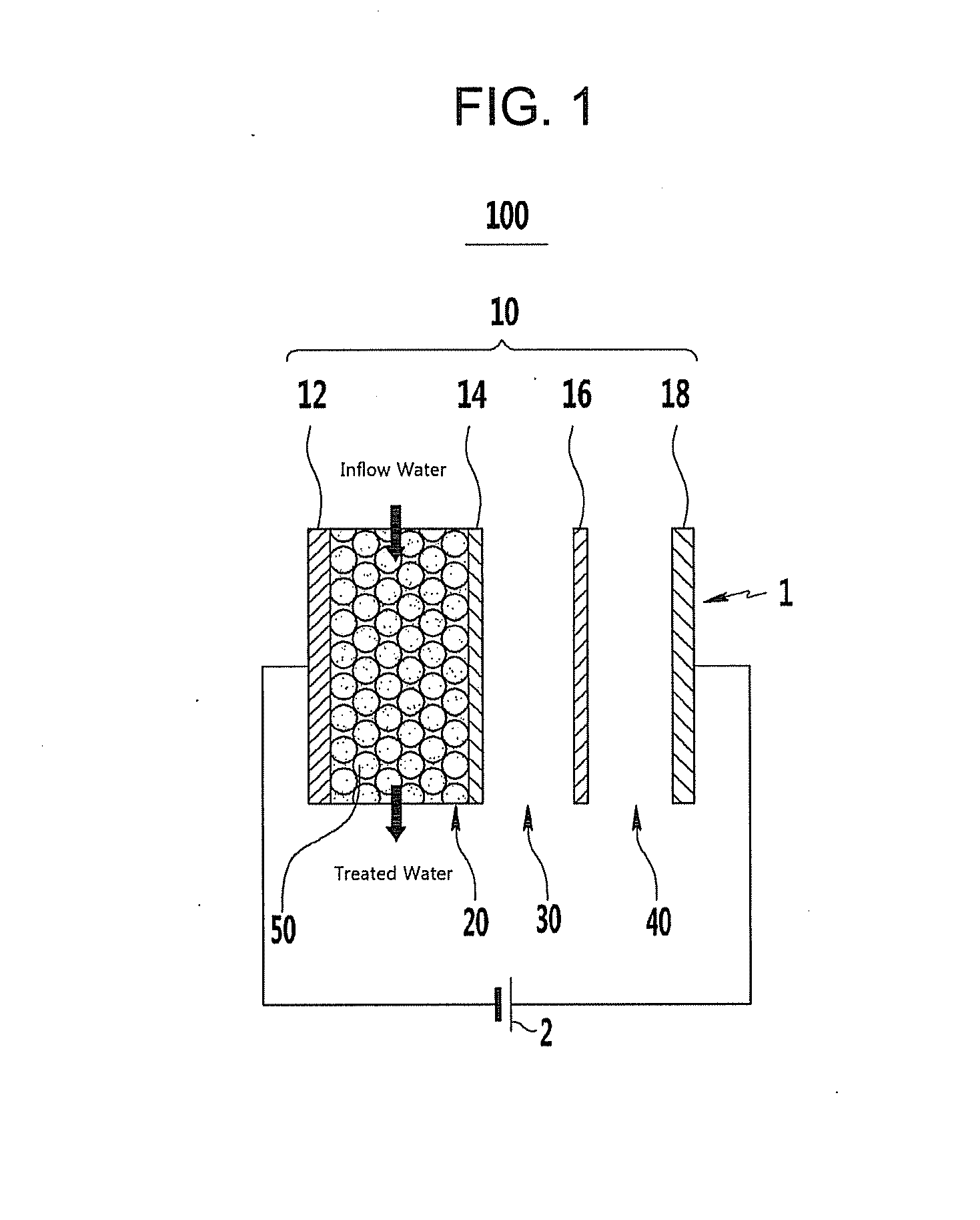
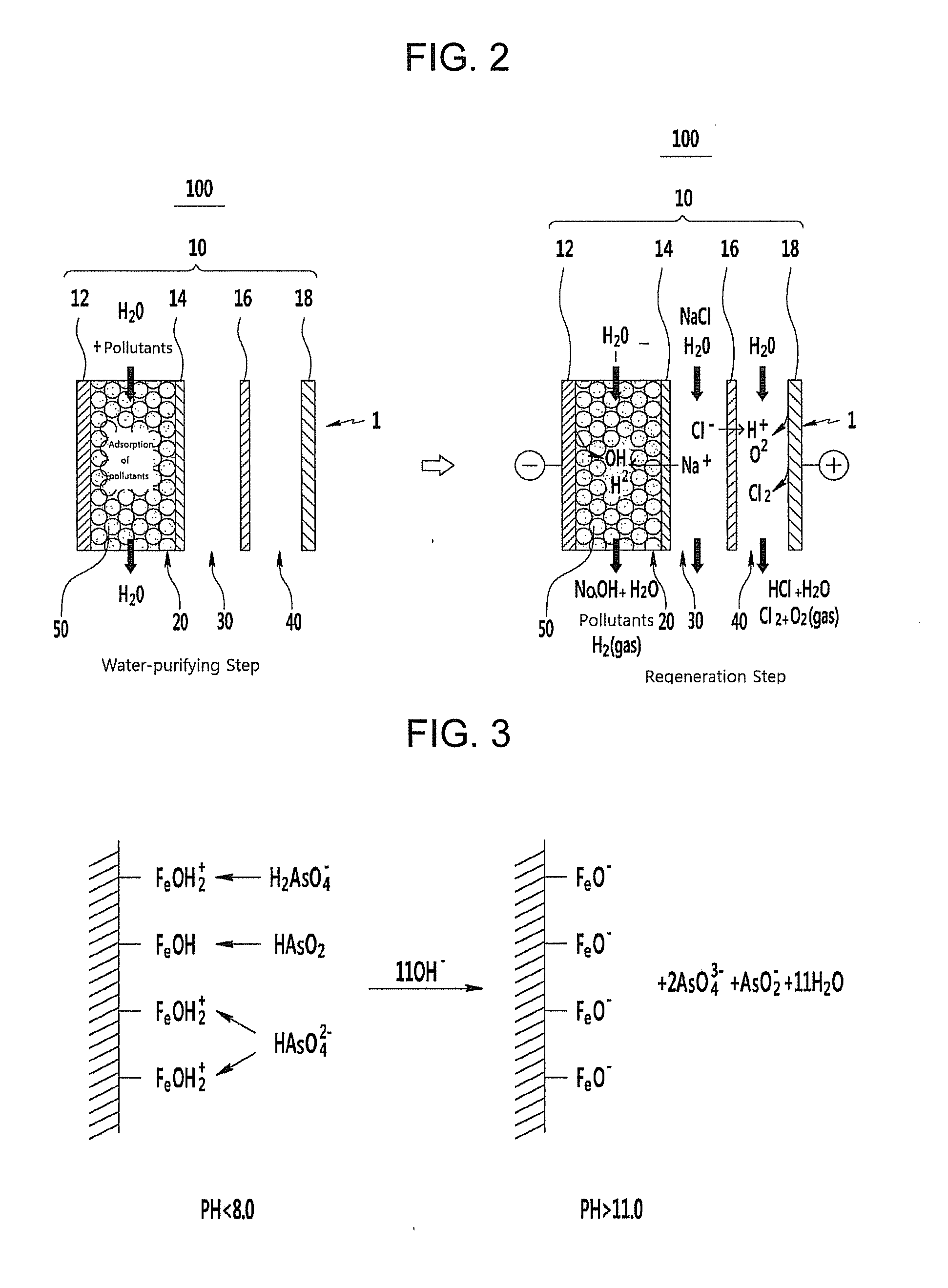
The patent text describes a regenerable and environmentally-friendly filter system with reduced maintenance costs for users. The filter unit includes an electrode structure with a cathode, cation exchange membrane, anion exchange membrane, and an anode. The filter system also includes a pH adjusting chamber and a voltage applier to induce water decomposition. The filter system can regenerate the water-purifying flow path without decomposing the system. The technical effects of the patent text include reduced maintenance costs, improved environmental friendliness, and efficient water purification.

Problems solved by technology

Particularly, an element such as arsenic (As) which may present a fatal level of toxicity to humans may be in the underground water, surface water, and the like.
Such by-products may not be completely removed and may remain in the water supplied to homes.
However, since most filters used in the water-purifying technology are consumable parts, periodic replacement is required, thereby generating added costs and inconvenience to users.
The replaced filter should also be discarded, thus causing another environmental problem.

Method used


Image

  • Regenerable Filter Unit, Regenerable Filter System Including The Same, And Method Of Operating Regenerable Filter System
  • Regenerable Filter Unit, Regenerable Filter System Including The Same, And Method Of Operating Regenerable Filter System
  • Regenerable Filter Unit, Regenerable Filter System Including The Same, And Method Of Operating Regenerable Filter System

Examples


experimental example

[0073]Manufacture of a Chloroform Filter System

[0074]A commonly-used activated carbon cloth CH900, a commonly-used cation exchange membrane ASTOM CMX, a commonly-used anion exchange membrane ASTOM AMX, and a commonly-used activated carbon cloth CH900 are cut to about 15×9 cm2, and then sequentially deposited and joined with a screw to manufacture a filter unit. A voltage applier is then connected to manufacture a filter system.

[0075]Evaluation of Chloroform Adsorption and Regeneration Performances

[0076]The operation of the system is performed at room temperature, and inflow water is prepared such that the concentration of chloroform is about 300 ppb in distilled water. The inflow water is supplied to the water-purifying flow path (cathode chamber) of the filter system at a flow rate of about 2.7 mL / min.

[0077]The concentration of residual chloroform is measured over time to confirm the change in chloroform removal capacity, and when the chloroform removal capacity decreases to about ...


PUM

PropertyMeasurementUnit
voltageaaaaaaaaaa
voltageaaaaaaaaaa
adsorption functionaaaaaaaaaa

Abstract

A filter unit may include an electrode structure, a fluid-purifying flow path, and a pH adjusting chamber. The electrode structure may include a cathode, a cation exchange membrane, an anion exchange membrane, and an anode in that order. The fluid-purifying flow path may be at least one of a path in the cathode, between the cathode and the cation exchange membrane, between the anion exchange membrane and the anode, and in the anode. The fluid-purifying flow path may include an adsorption function. The pH adjusting chamber may be between the cation exchange membrane and the anion exchange membrane. The pH adjusting chamber may be configured to control the pH of the fluid in the fluid-purifying flow path.

Description

CROSS-REFERENCE TO RELATED APPLICATION[0001]This application claims priority under 35 U.S.C. §119 to Korean Patent Application No. 10-2011-0022293, filed in the Korean Intellectual Property Office on Mar. 14, 2011, the entire contents of which are incorporated herein by reference.BACKGROUND[0002]1. Field[0003]Various example embodiments relate to a regenerable filter unit, a filter system, and a method of operating the same. More particularly, various example embodiments relate to an in-situ regenerable filter unit, a filter system, and a method of operating the same.[0004]2. Description of the Related Art[0005]Rapid industrialization is aggravating the pollution of water sources such as underground water, surface water, and the like. Particularly, an element such as arsenic (As) which may present a fatal level of toxicity to humans may be in the underground water, surface water, and the like.[0006]Polluted water may be taken and purified in a water purifying plant and then supplied...

Claims


Application Information

Patent Timeline
Patent Type & Authority Applications(United States)
IPC IPC(8): C02F1/42C02F1/66
CPCB01D61/00B82Y30/00B01D61/445B01D2311/2626B01D2313/345B01D2313/36B01D2313/40B01J20/06B01J20/08B01J20/10B01J20/12B01J20/18B01J20/20B01J20/3204B01J20/3234B01J20/3416B01J20/3441B01J2220/42C02F1/28C02F1/281C02F1/283C02F1/285C02F1/288C02F1/42C02F1/46104C02F1/469C02F1/66C02F2001/46119C02F2101/103C02F2101/12C02F2101/20C02F2101/36C02F2201/003C02F2201/46115C02F2201/46135C02F2201/46145C02F2201/4615C02F2201/4618C02F2209/05C02F2301/08C02F2303/16C02F2305/08B01J20/02B01J20/28007B01J20/3433B01J20/205B01J47/08B01J49/0052B01D61/44B01J49/30B01D35/06
Inventor KIM, CHANG HYUNKIM, HYUN SEOKKANG, HYO RANGYANG, HO JUNGLEE, JOO WOOKKWON, BOK SOONKIM, JAE EUN
Owner SAMSUNG ELECTRONICS CO LTD
Learn More