
Vehicular heating system

a heating system and foot technology, applied in the field of vehicles, can solve the problems of insufficient or too high temperature sense at the feet, and achieve the effects of raising the temperature of the foot area, quick warming, and quick warming

Inactive Publication Date: 2012-09-20
DENSO CORP
View PDF6 Cites 39 Cited by
  • Summary
  • Abstract
  • Description
  • Claims
  • Application Information

AI Technical Summary

Benefits of technology

[0007]Due to this, it is possible to perform control while linked with the car air-conditioner, obtain a satisfactory warmness sense level at the feet, and reduce fuel consumption.
[0009]Due to this, by controlling the ratio between the foot vent heat Qf which the foot vent air flow has and the input electric power Q of the radiative heater so as to give the same warmness sense level at the feet of the passenger and using a radiative heater with a large impact on the warmness sense level even with a small input electric power, the fuel efficiency is increased.
[0011]Due to this, by controlling the ratio between the foot vent heat Qf which the foot vent air flow has and the input electric power Q of the radiative heater so as to give the same warmness sense level at the feet of the passenger and using a radiative heater with a large impact on the warmness sense level even with a small input electric power, the fuel efficiency is increased and it is not necessary to run the engine just for passenger compartment air-conditioning control.
[0020]Due to this, to enable safe use without concern about high temperature burn injuries or low temperature burn injuries, no matter how the temperature information inside the passenger compartment is set, the temperature of the heating element 2 of the radiative heater 1 is automatically controlled to always be no more than the threshold temperatures for high temperature burn injuries and low temperature burn injuries. Further, the radiative heater can sufficiently contribute to raising the temperature of the foot area in the transitional period and can maintain a predetermined warmness sense level without concern over low temperature burn injuries in the steady state period. The radiative heating enables the legs to be quickly warmed, so this is effective for the transitional period.
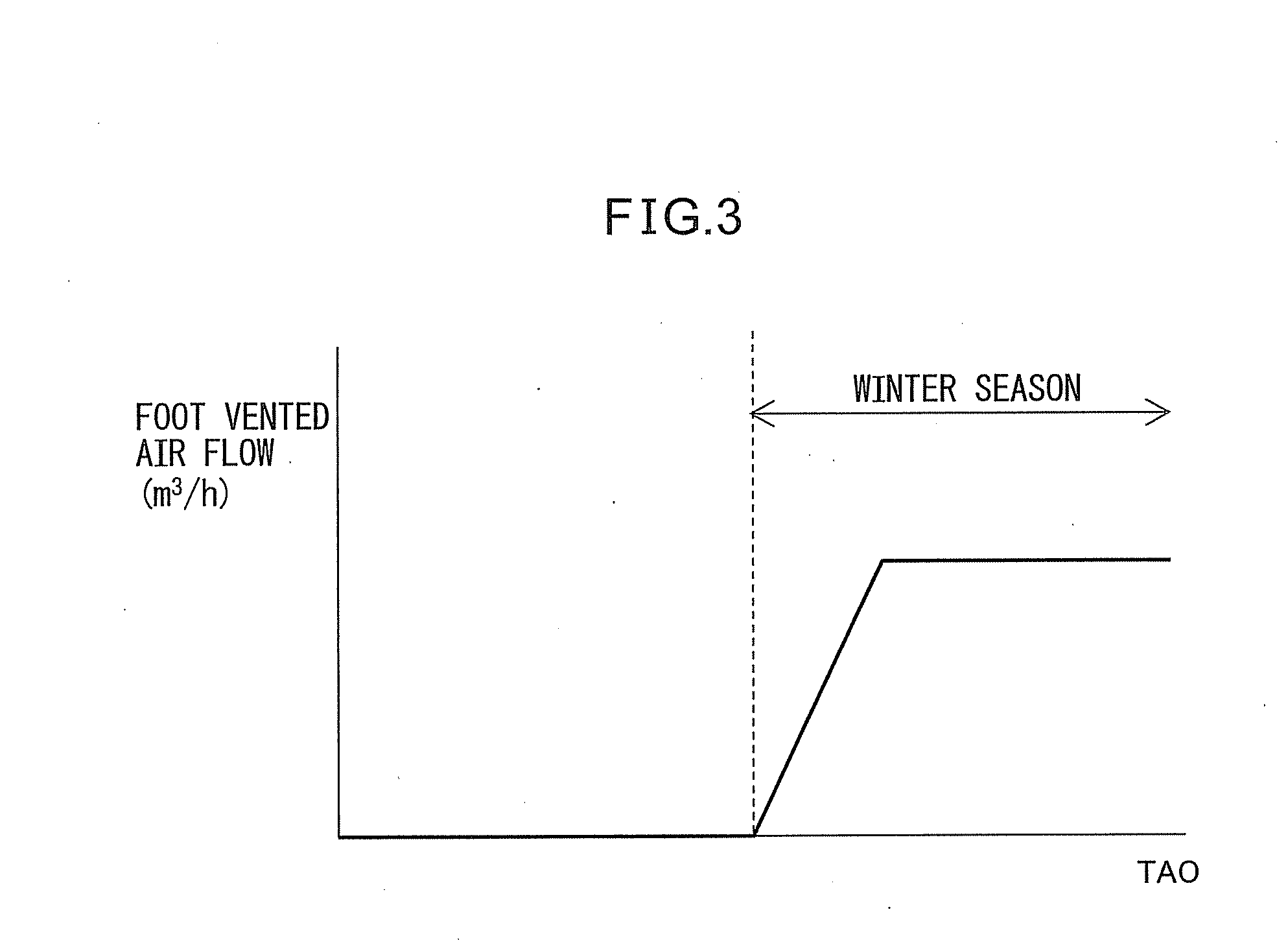
[0021]The aspect of the invention of claim 13 provides the aspect of the invention as set forth in claim 12, wherein the temperature information inside the passenger compartment is the target blowing-out temperature of the air-conditioning unit which controls the passenger compartment air-conditioning in accordance with information on the environment inside and outside of the passenger compartment. Due to this, it is possible to control the surface member temperature of the heating element of the heating system while linked with the value of the target blowing-out temperature in the case of automatic air-conditioning control so as to enable safe use without concern over high temperature burn injuries and low temperature burn injuries. In the winter season right after a passenger gets in the vehicle and feels cold due to the passenger compartment not being warmed up, the value of the target blowing-out temperature rises to a high temperature, but even in this case, the radiative heater is controlled to a high temperature not causing high temperature burn injuries and therefore the passenger compartment and foot area are quickly warmed. After this, as the value of the target blowing-out temperature TAO falls, the surface member temperature of the heating element of the radiative heater also automatically falls by the same timing, so the feet can be efficiently heated. Therefore, it is possible to maintain a constant warmness sense level at the foot area. Further, there is no waste in the heating by the radiative heater, so energy is saved.

Problems solved by technology

However, in this related art, if considering the air temperature inside of the passenger compartment or simultaneously using the planar heating element and the car air-conditioner without linkage with the car air-conditioner, there was the problem that the warmness sense level at the feet would be insufficient or too high.

Method used


Image

  • Vehicular heating system
  • Vehicular heating system
  • Vehicular heating system

Examples


first embodiment

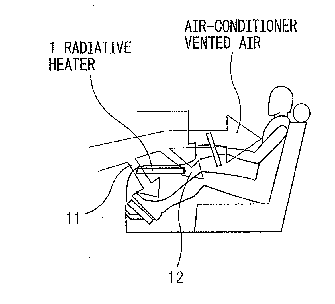
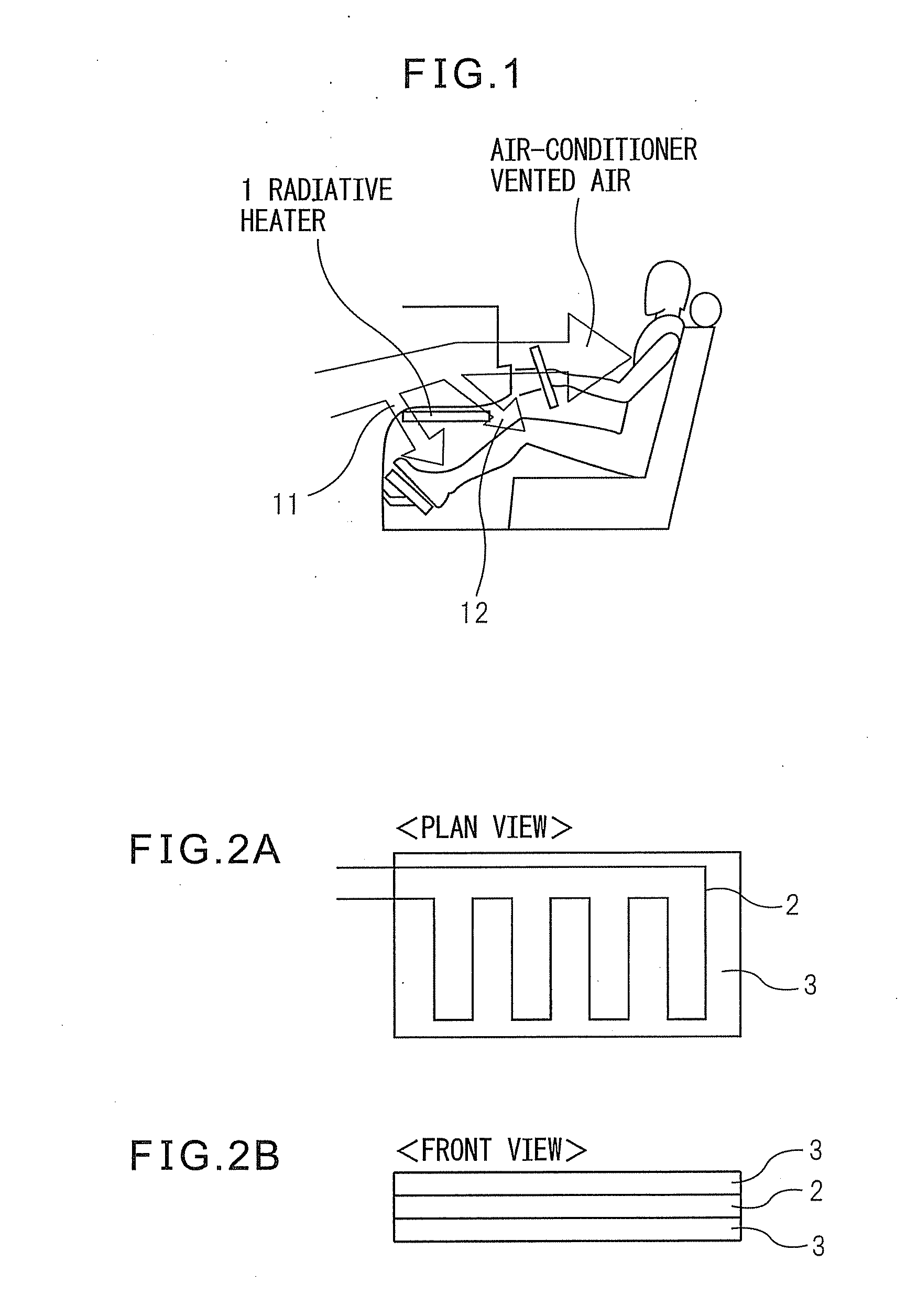
[0045]Next, the unique features of radiative heating will be explained, then an embodiment of the present invention will be explained. As shown in FIGS. 2A and 2B, the radiative heater 1 in one embodiment of the present invention is placed near the top of the feet of the driver in the wall surface under the steering wheel column of the vehicle. This efficiently heats the foot parts, which are particularly susceptible to cold and heat in the body, locally by mainly radiant energy.

[0046]This embodiment of the present invention makes good use of such features of the radiative heater and aims at satisfying the warmness sense level of the feet while realizing fuel savings by control linked with the car air-conditioner.

[0047]An electric heater or other radiative heater uses radiative heat for heating. Therefore, unlike when blowing warm air to warm the legs, a small amount of heat gives the same warmness sense level, so the thermal efficiency is good. A warmness sense level obtained by co...

second embodiment

[0055]The next second embodiment considers not only the fuel efficiency due to the characteristics of the radiative heater, but also the characteristics of the vehicle so as to control the passenger compartment air-conditioner and the radiative heater. The air-conditioning unit (HVAC) houses a heater core which acts as a heat exchanger for heating use. This heater core uses the cooling water (warm water) of the vehicle driving motor as a heat source for heating the air. When the engine water temperature of the cooling water of the engine is around a certain predetermined threshold value and the heat source which is used for heating is switched as explained next, the thermal efficiency rises and in turn the fuel economy can be realized.

[0056]When utilizing the heater core of the air-conditioning unit (HVAC) for heating, if there is an extra margin of heat as a heat source in the cooling water (warm water) (when the engine water temperature is a certain predetermined value or more), n...

third embodiment

[0069]As shown in FIGS. 2A and 2B, when using the radiative heater 1, it is necessary that it be able to be used safely without concern over high temperature burn injuries and low temperature burn injuries. “High temperature burn injuries” mean burn injuries which instantaneously are caused, while “low temperature burn injuries” are burn injuries in which for example the skin is in contact with a 44° C. heat source for 6 hours whereupon the cells at that part are destroyed down deep under the skin resulting in burn injuries.

[0070]It is known that right after a passenger gets in a vehicle in the winter season, he or she easily feels cold due to the passenger compartment not being warmed up. Therefore, in particular, the foot parts are heated by local radiative heating using the radiative heater 1. In such a case, at the start of the heating, there is a concern that the temperature of the heating element 2 of the radiative heater 1 will rapidly rise and cause high temperature burn inj...


PUM


Abstract

A vehicular heating system comprising a passenger compartment air-conditioner and a radiative heater which heats a foot area of a passenger, said vehicular heating system detecting foot vent heat which said foot vent air flow has and controlling said passenger compartment air-conditioner and said radiative heater in accordance with that heat.

Description

BACKGROUND OF THE INVENTION[0001]1. Field of the Invention[0002]The present invention relates to a vehicular heating system which controls a radiative heater and a car air-conditioner linked with each other.[0003]2. Description of the Related Art[0004]In the past, it has been known to place a planar heating element near a foot area of a seat of a vehicle. Japanese Unexamined Patent Publication No. 2010-64681 discloses a vehicular heating system which arranges a planar heating element in an instrument panel of a vehicle so as to heat the inside of the passenger compartment. This planar heating element is arranged in the instrument panel corresponding to the knee to foot part of a seat passenger. At a location corresponding to the foot part side away from the knee part side, the heating density of the planar heating element is raised. Due to this, the surface temperature of the foot part side is raised compared with the knee part side to apply a larger radiative heat from the foot par...

Claims


Application Information

Patent Timeline
IPC IPC(8): F24D19/10
CPCF24H3/002B60H2001/225B60H1/2218F24H3/102B60H1/0073B60H1/2226
Inventor OKAMOTO, ASAMIOTA, KOJI
Owner DENSO CORP
Learn More