Coupling structure for airframe components

a technology of airframe components and coupling structures, which is applied in the direction of aircraft static dischargers, threaded fasteners, transportation and packaging, etc., can solve the problem that the fastener member cannot reliably suppress the occurrence of electric arcs, and achieve the effect of sufficient lightning protection capability and high reliability

Active Publication Date: 2012-09-20
MITSUBISHI AIRCRAFT
View PDF5 Cites 11 Cited by
  • Summary
  • Abstract
  • Description
  • Claims
  • Application Information

AI Technical Summary

Benefits of technology

[0023]In addition, in the case where a plurality of the fastener members are arranged in a plurality of lines along the end part of the member located on the inner side of the airframe among the plurality of members, the conductive area may be formed in outer peripheral parts of fastener members arranged in a line far from the end part of the member located on the inner side of the airframe among the fastener members arranged in the plurality of lines. This allows a lighting current caused at the time of a lightning strike to flow from one member to another member in a portion of the conductive area far from the end part of the member located on the inner side of the airframe. Accordingly, the lightning current can be suppressed from flowing near the end part of the member located on the inner side of the airframe.
[0024]Here, the conductive area may be formed in a ring-shaped pattern around each of the outer peripheral parts of the fastener members. With this configuration, in the state where the plurality of members are fastened to each other by the fastener member, the fastening power of the fastener member brings the conductive area into close contact with the members sandwiching the conductive area, thereby reliably achieving the electrical conduction.
[0025]The inside of an airframe component, for example, a wing, which is obtained by placing a plurality of members on top of each other and coupling the members to each other, may function in some cases as a fuel tank or other such space in which fuel and fuel vapor exist. In this case, the lightning current can be effectively suppressed from flowing near the end part of the member located on the inner side of the airframe.
[0026]According to the present invention, the electrical conduction between the plurality of members can be achieved by the conductive area formed in the portion in which the plurality of members are opposed to each other. As a result, a lightning current flowing along a surface of one member located on the outer side of the airframe at the time of a lightning strike can flow into another member through the conductive pattern part without passing through the fastener member, so that the tolerable amount of current in the overlapped portion of the plurality of members can be enhanced.
[0028]With these features, an electric arc can be suppressed from occurring on the internal space side of the wing, so that sufficient lightning protection capability can be ensured.
[0029]Then, such a configuration as described above is used in combination with other occurrence suppressing means and sealing means for an electric arc at the time of a lightning strike. As a result, even if any of the means cannot provide a required function, the required function can be compensated, so that a high reliability can be ensured.

Problems solved by technology

Hence, in the case where an electrical conduction function of the fastener member 1 is impaired, the sealant or the cap provided at the leading end part of the fastener member may not reliably suppress the occurrence of the electric arc A.

Method used


Image

  • Coupling structure for airframe components
  • Coupling structure for airframe components
  • Coupling structure for airframe components

Examples


first embodiment

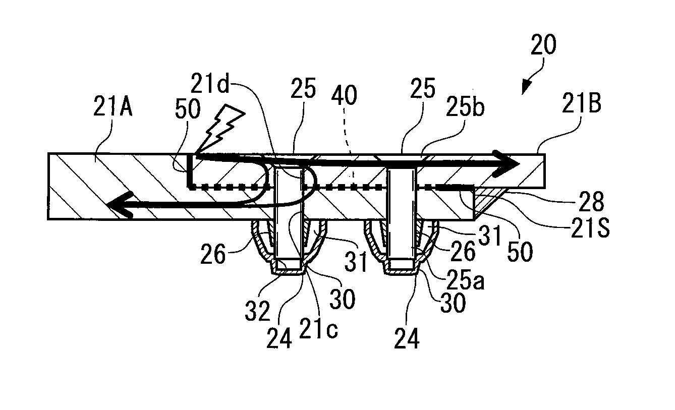
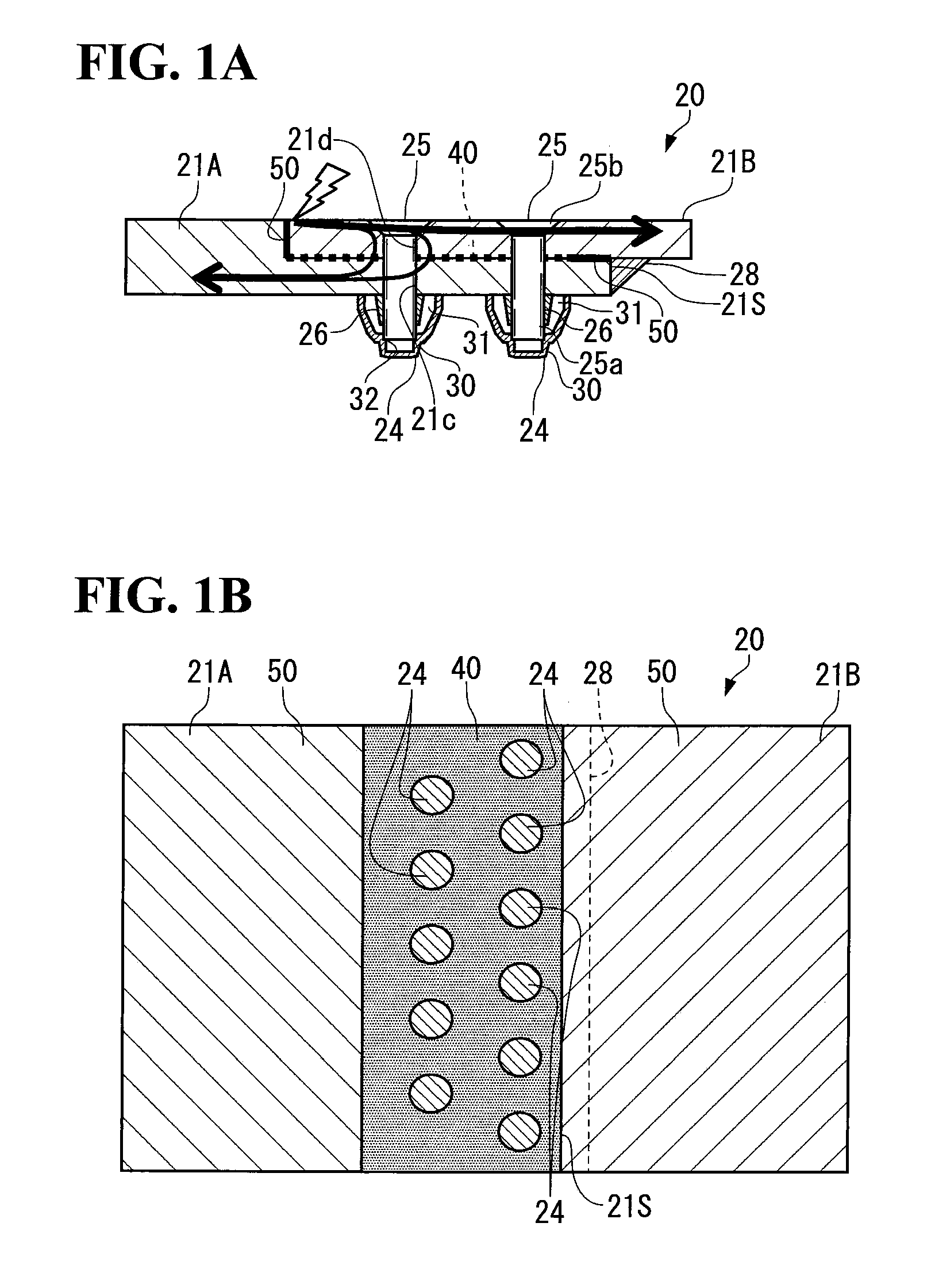
[0036]FIGS. 1A and 1B are a cross-sectional view and a plan view each illustrating part of a wing constituting the airframe of an aircraft to which a coupling structure for airframe components is applied according to a first embodiment of the present invention.

[0037]As illustrated in FIG. 1A, the outer frame of a wing 20 is formed by coupling a plurality of wing surface panels (members) 21A, 21B, . . . , and the wing surface panels 21A, 21B . . . are made of, for example, metal materials such as an aluminum alloy, carbon fiber reinforced plastics (CFRP) that are composite materials of carbon fiber and resin, and glass fiber reinforced plastics (GFRP) that are composite materials of glass fiber and resin. Then, end parts of the adjacent wing surface panels 21A and 21B are placed on top of each other, and the adjacent wing surface panels 21A and 21B are coupled to each other by a plurality of fastener members 24 in the overlapped portion thereof.

[0038]Each fastener member 24 includes ...

second embodiment

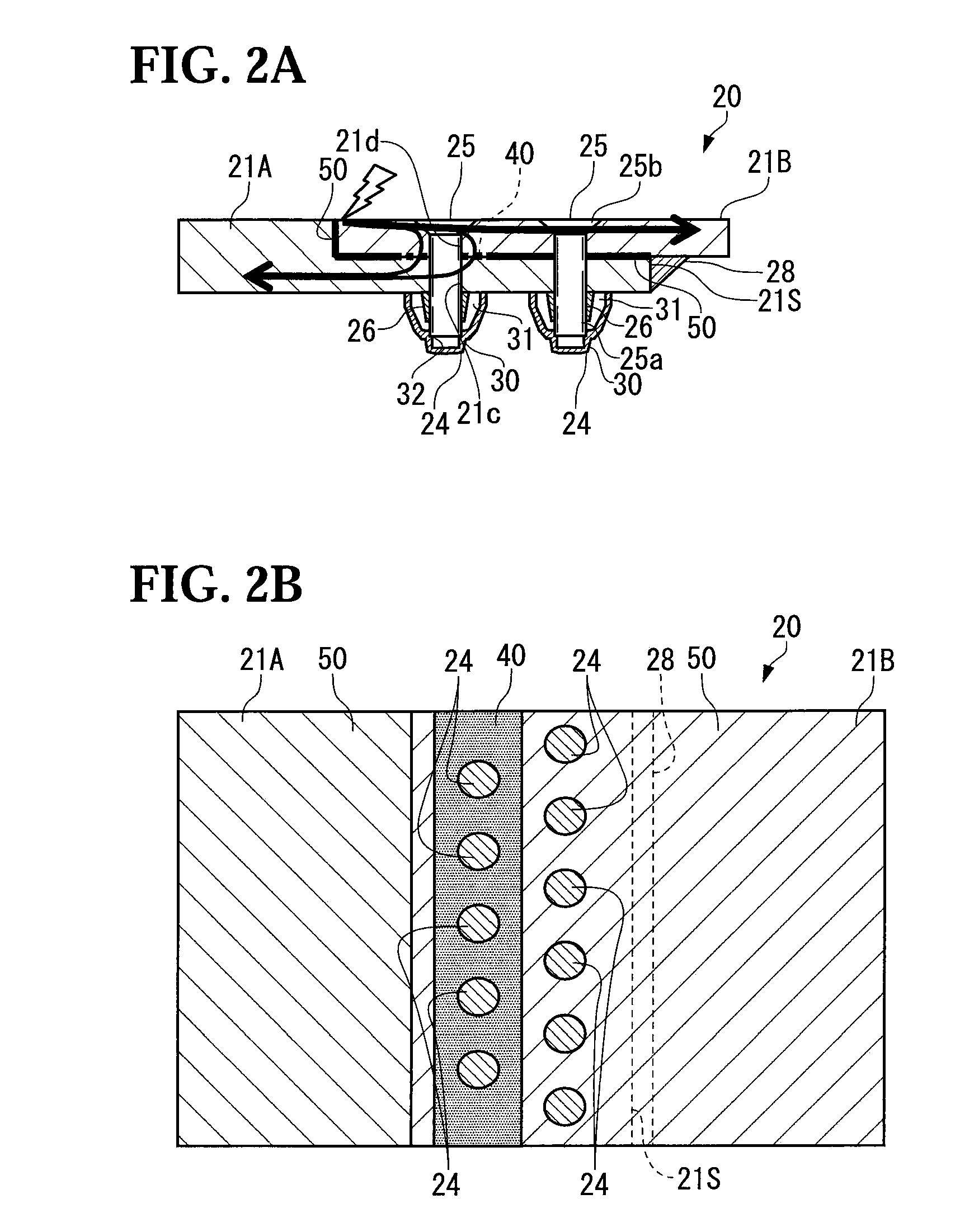
[0063]In a second embodiment of the present invention, as illustrated in FIGS. 2A and 2B, the conductive pattern part 40 is formed in a continuous belt-like pattern along the outer shape of the wing surface panel 21B, only in a region corresponding to the fastener members 24 that are arranged in a line far from the boundary portion between the end part 21S of the wing surface panel 21A and the wing surface panel 21B, in the overlapped portion of the wing surface panels 21A and 21B.

[0064]With this configuration, the lightning current L flowing along the surface of the wing surface panel 21B at the time of a lightning strike can flow into the wing surface panel 21A through the conductive pattern part 40 formed in the region corresponding to the fastener members 24 that are arranged in the line far from the boundary portion between the end part 21S of the wing surface panel 21A and the wing surface panel 21B.

[0065]The primer layer 50 as the insulating area is formed in a belt-like patt...

third embodiment

[0068]In a third embodiment of the present invention, as illustrated in FIGS. 3A and 3B, the conductive pattern part 40 is formed only around each of the fastener members 24 that are arranged in a line far from the boundary portion between the end part 21S of the wing surface panel 21A and the wing surface panel 21B, of all the fastener members 24 that are arranged in the plurality of lines along the boundary portion between the end part 21S of the wing surface panel 21A and the wing surface panel 21B, in the overlapped portion of the wing surface panels 21A and 21B. The conductive pattern part 40 is not formed around each of the fastener members 24 arranged in the other lines, and the primer layer 50 is formed in outer peripheral parts thereof. The conductive pattern part 40 is formed, for example, in a ring-shaped pattern around each of the holes 21c and 21d on the plane on which the wing surface panel 21A and the wing surface panel 21B abut against each other.

[0069]With this conf...


PUM


Abstract

Provided is a coupling structure for airframe components that is capable of ensuring sufficient lightning protection capability. A conductive pattern part 40 made of a conductive material is formed around each fastener member 24 between wing surface panels 21A and 21B. The conductive pattern part 40 is formed, for example, around each of holes 21c and 21d on the plane on which the wing surface panel 21A and the wing surface panel 21B abut against each other. Then, the conductive pattern part 40 is pushed against both the wing surface panel 21A and the wing surface panel 21B by the fastening power of the fastener members 24, whereby electrical conduction between the wing surface panel 21A and the wing surface panel 21B can be achieved.

Description

BACKGROUND OF THE INVENTION[0001]1. Field of the Invention[0002]The present invention relates to a coupling structure for airframe components such as wing surface panels constituting the airframe of an aircraft.[0003]2. Description of the Related Art[0004]In general, a wing constituting the airframe of an aircraft has a hollow structure, and a surface of the wing is formed of a plurality of wing surface panels. Then, two adjacent wing surface panels are coupled to each other by a fastener member (securing piece).[0005]At this time, the two wing surface panels are coupled to each other by the fastener member in the following manner. That is, a pin-shaped fastener main body is inserted from the outer side of the wing into through-holes that are respectively formed on both the wing surface panels placed on top of each other. Then, the leading end part of the fastener main body is fixed by a fixing piece on the inner side of the wing.[0006]Meanwhile, aircraft need to be fully prepared f...

Claims


Application Information

Patent Timeline
Patent Type & Authority Applications(United States)
IPC IPC(8): B64C1/06B64D45/02
CPCB64C3/34B64D45/02F16B5/02F16B15/02F16B2001/0064H05H3/02H01R4/06F16B37/14F16B2200/93
Inventor KAWAHARA, KOJIYAMAKOSHI, HIDEOKAMINO, YUICHIROIYOMASA, ATSUHIROHASHIGAMI, TORU
Owner MITSUBISHI AIRCRAFT
Why Eureka
Try Eureka