Infrared gas detector and infrared gas measuring device

a technology of infrared gas and measuring device, which is applied in the direction of optical radiation measurement, instruments, and sensing radiation from gases/flames, etc., can solve the problems of increased temperature of transmission filter and cut-off filter, and difficult thermal insulation, etc., to achieve improved sensitivity and cost reduction

Inactive Publication Date: 2012-09-20
PANASONIC CORP
View PDF7 Cites 40 Cited by
  • Summary
  • Abstract
  • Description
  • Claims
  • Application Information

AI Technical Summary

Benefits of technology

[0005]In view of the above insufficiency, the present invention has been aimed to propose an infrared gas detector and

Problems solved by technology

Therefore, an increase of a heat capacity makes ensuring thermal insulation difficult, and therefore the response performan

Method used


Image

  • Infrared gas detector and infrared gas measuring device
  • Infrared gas detector and infrared gas measuring device
  • Infrared gas detector and infrared gas measuring device

Examples


first embodiment

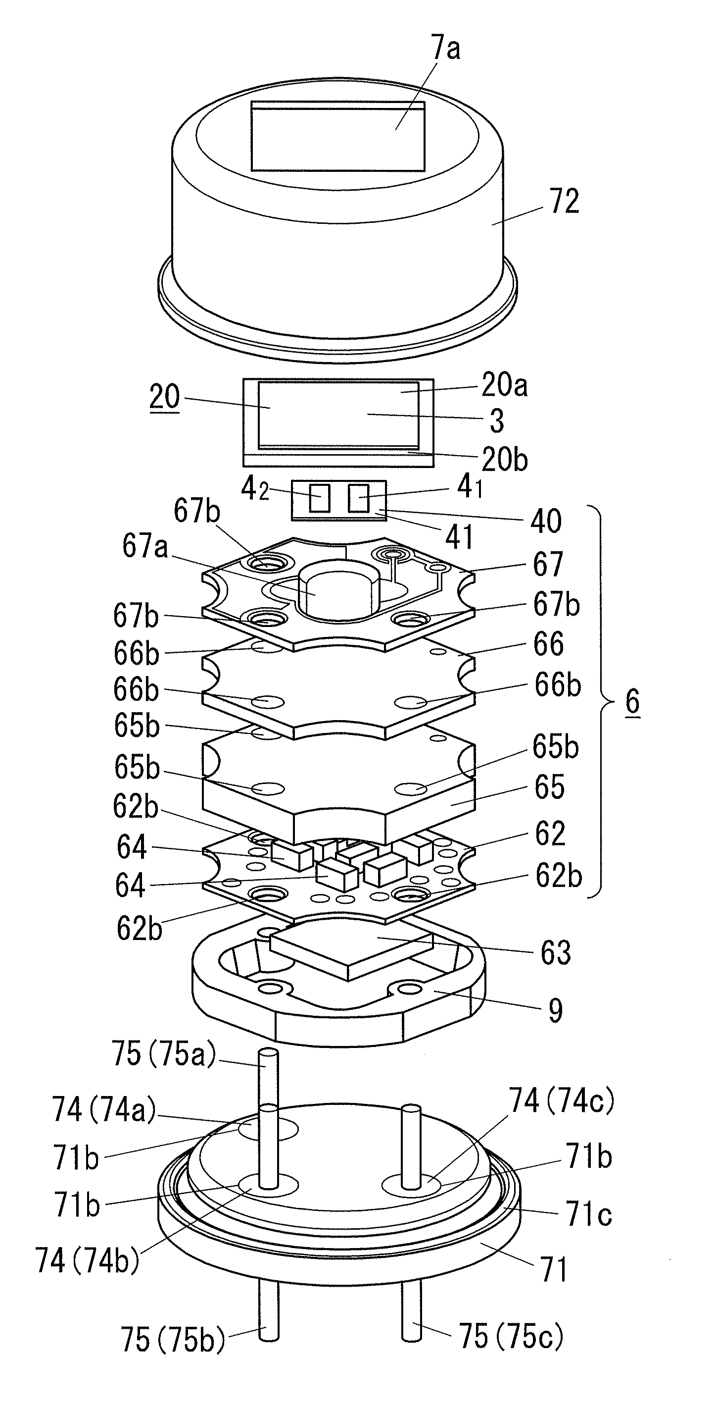
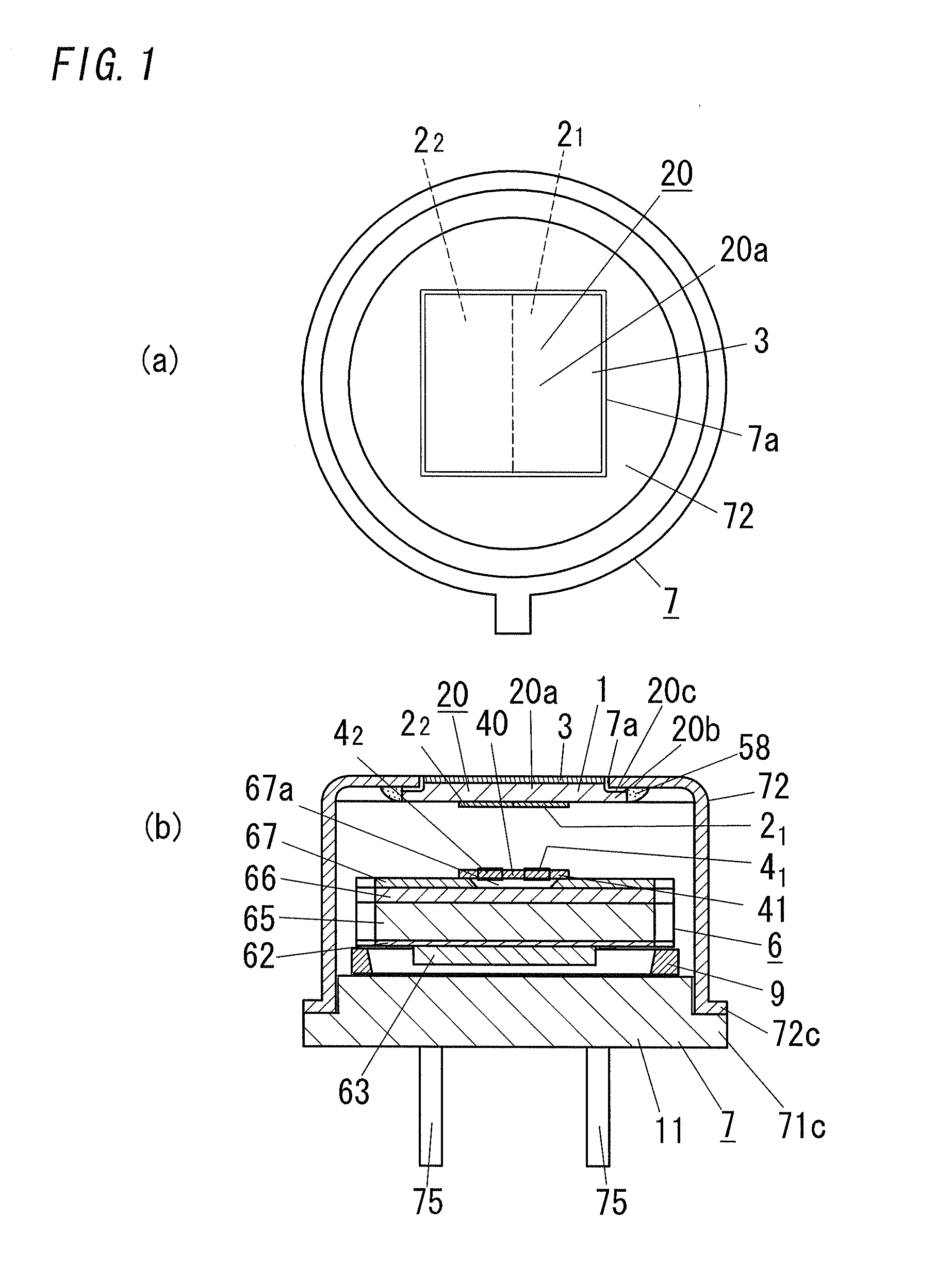
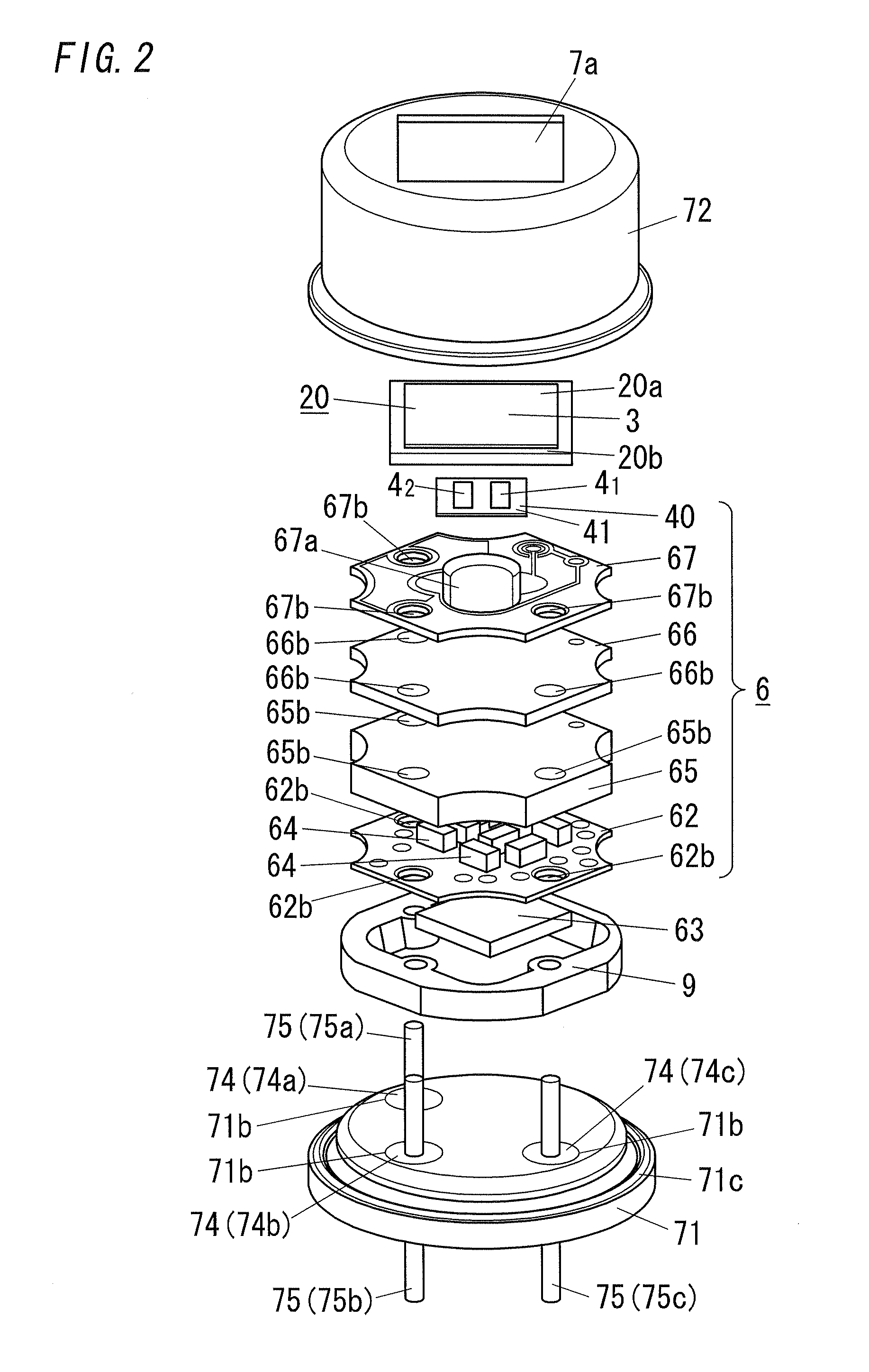
[0063]As shown in FIGS. 1 and 2, the infrared gas detector (infrared reception unit) of the present embodiment includes a circuit block 6 and a package 7. The circuit block 6 includes an infrared reception element (infrared reception member) 40 and a signal processing circuit. The infrared reception member 40 includes plural (two) pyroelectric elements 41 and 42. The signal processing circuit is configured to make signal processing with regard to an output of the infrared reception element 40. The package 7 is a can package configured to accommodate the circuit block 6. Besides, in the present embodiment, each of the pyroelectric elements 41 and 42 is a thermal infrared detection element which is used for sensing infrared on the basis of heat applied thereto.

[0064]The package 7 includes a stem 71 and a cap 72 which are made of a metal. Although the circuit block 6 is mounted on the stem 71, a spacer 9 made of a dielectric material is interposed between the circuit block 6 and the st...

second embodiment

[0149]In the present embodiment, an explanation is made to an infrared gas measuring device applied to a gas leakage alarm, for example. Such an infrared gas measuring device includes an infrared light source 1001 and an infrared sensor (infrared detector) 1002, as shown in FIG. 30. The infrared light source 1001 is configured to emit infrared in response to receiving an electric signal. The infrared sensor 1002 is configured to detect infrared. Interposed between the infrared light source 1001 and the infrared sensor 1002 is a gas detection tube 1003. A detection target gas (measurement gas) is flowed into the gas detection tube 1003. Besides, the infrared detector as described in the first embodiment can be adopted as the infrared sensor 102.

[0150]The gas detection tube 1003 includes a conduit 1031 configured to guide infrared from the infrared light source 1001 to the infrared sensor 1002. The conduit 1031 has its inner surface configured to reflect infrared. For example, a refle...


PUM


Abstract

An infrared gas detector includes an infrared reception member, a package configured to accommodate the infrared reception member, and an optical filter. The infrared reception member includes a plurality of thermal infrared detection elements each configured to detect infrared based on heat caused by received infrared. The thermal infrared detection elements are placed side by side. The package is provided with a window opening configured to allow the infrared reception member to receive infrared. The optical filter is attached to the package so as to cover the window opening, and includes a plurality of filter elements respectively corresponding to the plurality of the thermal infrared detection elements. Each of the filter elements includes a filter substrate made of an infrared transparent material, a transmission filter configured to transmit infrared of a selected wavelength, and a cut-off filter configured to absorb infrared of a wavelength longer than the selected wavelength. The transmission filter and the cut-off filter are formed over the filter substrate. The filter substrate is thermally coupled to the package. The transmission filters of the respective filter elements are configured to transmit infrared of the different selected wavelengths.

Description

TECHNICAL FIELD[0001]The present invention is directed to infrared gas detectors and infrared gas measuring devices.BACKGROUND ART[0002]In the past, there has been proposed an infrared gas measuring device designed to measure a gas based on the principle that a gas absorbs infrared with a specific wavelength. The infrared gas measuring device measures an absorbance of infrared (infrared ray) with an absorption wavelength depending on a molecular structure of a gas to be measured, and calculates a concentration of the gas on the basis of the measured absorbance (see JP 07-72078 A, JP 03-205521 A, and JP 10-281866 A).[0003]JP 07-72078 A discloses an infrared gas detector including a filter configured to transmit infrared with a specific wavelength and a pyroelectric photodetector configured to detect infrared which has been transmitted by the filter. The filter is formed on the pyroelectric photodetector directly. Therefore, an increase of a heat capacity makes ensuring thermal insula...

Claims


Application Information

Patent Timeline
IPC IPC(8): G01N21/59G01J5/00
CPCG01J5/0014G01J5/02G01J5/024G01J5/04G01J5/045G01N21/359G01J5/0803G01J5/0862G01J5/12G01J5/20G01N21/3504G01J5/08G01J5/0802G01N21/37G01N21/61
Inventor NISHIKAWA, TAKAYUKIWATABE, YOSHIFUMIINABA, YUICHIHIRAI, TAKAHIKOKITAMURA, HIROAKI
Owner PANASONIC CORP
Why Eureka
Try Eureka