Spread spectrum clock generator

a generator and spectrum spectrum technology, applied in the direction of electrical equipment, pulse automatic control, etc., can solve the problems of fine frequency variation, fine frequency variation cannot be realized, mismatches in changing the division ratio of frequency dividers, etc., and achieve the effect of reducing the jitter of the output clock signal

Active Publication Date: 2012-09-20
RICOH KK
View PDF5 Cites 38 Cited by
  • Summary
  • Abstract
  • Description
  • Claims
  • Application Information

AI Technical Summary

Benefits of technology

[0016]The present invention aims to provide a spread spectrum clock generator which includes a novel fractional PLL circuit which does not operate by changing the division ratio of the frequency divider and can decrease jitters in the output clock signal.

Problems solved by technology

Because of this, it faces a problem that due to the narrow bandwidth of the loop filter 23, a system correction amount to deal with a fluctuation cannot be large, which causes deterioration in jitter characteristic.
Another problem is that the conventional SSCG can vary the frequency only on a pixel clock signal basis so that fine frequency variation cannot be realized.
Another problem is that in the fractional PLL circuit phase mismatches occur in changing the division ratio of the frequency divider 26.
This causes spurious components to enter the output clock signal vco_ck and deteriorate the jitter characteristic of the output clock signal vco_ck.
This increases the phase noise in the voltage controlled oscillator 24a and degrades jitter characteristic.

Method used


Image

  • Spread spectrum clock generator
  • Spread spectrum clock generator
  • Spread spectrum clock generator

Examples


first embodiment

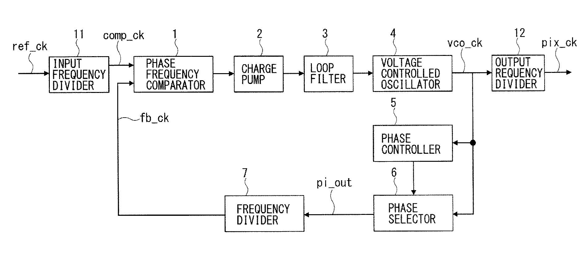
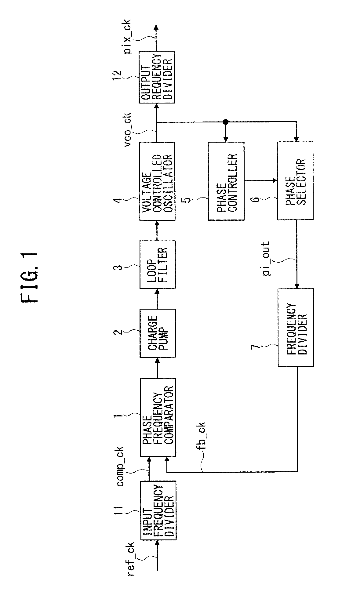
[0038]FIG. 1 is a block diagram of a spread spectrum clock generator as a fractional PLL circuit according to a first embodiment. A reference clock signal ref_ck generated by a not-shown clock generator is divided by an input frequency divider 11 to an input clock signal comp_ck and input to a phase frequency comparator 1. The phase frequency comparator 1 detects a phase difference between the input clock signal comp_ck and a feedback signal fb_ck and outputs it to a charge pump 22. The charge pump 22 increases or decreases a charge pump voltage in accordance with the phase difference and outputs it to a loop filter 23. The loop filter 23 outputs a control voltage in accordance with the charge pump voltage to a voltage controlled oscillator (VCO) 4. The voltage controlled oscillator (VCO) 4 generates and outputs an output clock signal vco_ck with a frequency and a phase in accordance with the control voltage. An output frequency divider 12 divides the output clock signal vco_ck for ...

second embodiment

[0054]Next, referring to FIG. 8 to FIG. 11, the SSCG's operation when any of the respective division ratios div_puck, div_fb, div_pll of the phase selector 6, output frequency divider 12, and frequency divider 7 is 1 or more is described. In the drawings a set value div_puck of the phase selector 6 is 2 and the division ratio thereof is 3.

[0055]FIG. 8 is a timing chart for the phase shift of the phase selector 6 of the spread spectrum clock generator according to a second embodiment of the present invention when a phase shift amount Δph is positive. The output clock signal vco_ck is divided by the phase selector 6 at every three clocks to clock signals div_ck. For example, the tenth to twelfth clocks vco_ck(9), vco_ck(10), vco_ck(11) of the output clock signal become the fourth clock div_ck(3) of the divided clock signal. Each clock of the output clock signal vco_ck is divided into three sub clocks vco_ck(0)′, vco_ck(1)′, vco_ck(2)′. In FIG. 8 the cycle of the phase shift clock sign...

third embodiment

[0078]FIG. 14 shows the spread spectrum modulation of the phase selector of the SSCG according to a third embodiment. The structure of the SSCG is the same as that of the SSCG in FIG. 1. In the present embodiment the SSCG is configured to compensate the coarseness of the frequency step of the SS modulation of the output clock signal vco_ck which may occur when a set value div_puck of the division ratio of the phase selector 6 is small and the minimal multiple rate of the frequency is large. This problem occurs because the resolution of the SS modulation depends on the division ratio of the phase selector 6 in the SSCG.

[0079]Referring to FIG. 14, the phase selector 6 is configured to change the phase shift amount Δph so that it gradually increases, by repeatedly switching the phase shift amounts before and after the change. In other words, the phase selector 6 modulates the step width for changing the phase shift amount Δph.

[0080]FIG. 15 is an enlarged view of an increase in the phas...


PUM


Abstract

A spread spectrum clock generator includes a phase comparator to detect a phase difference between a reference input clock signal and a feedback signal and output a control voltage, a voltage controlled oscillator to generate an output clock signal with a frequency in line with the control voltage, a phase selector to select any of equally divided phases of one cycle of the output clock signal, generate and transmit a phase shift clock signal to the phase comparator as the feedback signal, and a phase controller to decide a phase of the rising edge of the phase shift clock signal and control the phase selector to select the decided phase, and generate a second phase shift amount, decide the rising edge of the phase shift clock signal to and subject the output clock signal to spread spectrum modulation by the second phase shift amount.

Description

CROSS REFERENCE TO RELATED APPLICATION[0001]The present application is based on and claims priority from Japanese Patent Application No. 2011-059154, filed on Mar. 17, 2011, the disclosure of which is hereby incorporated by reference in its entirety.BACKGROUND OF THE INVENTION[0002]1. Field of the Invention[0003]The present invention relates to a spread spectrum clock generator (SSGC).[0004]2. Description of the Related Art[0005]In the art of a clock generator a spread spectrum clock generator (SSGC) is known. It aims to prevent electromagnetic interference (EMI) having a peak at a specific frequency by slightly modulating the frequency of a clock signal to spread the EMI energy to reduce a peak value. Japanese Patent Application Publication No. 2004-328280 and No. 2007-288375 disclose, as such an SSCG, a PLL (Phase Locked Loop) circuit or a fractional PLL circuit with a division ratio of a rational number, for example.[0006]FIG. 17 is a block diagram of a conventional spread spectr...

Claims


Application Information

Patent Timeline
Patent Type & Authority Applications(United States)
IPC IPC(8): H03L7/081
CPCH03L7/197H03L7/0891
Inventor HIRAI, KYOHKOKANNO, TOHRU
Owner RICOH KK
Why Eureka
Try Eureka