Device of phase locked-loop and the method using the same

Active Publication Date: 2012-09-20
REALTEK SEMICON CORP
View PDF3 Cites 5 Cited by
  • Summary
  • Abstract
  • Description
  • Claims
  • Application Information

AI Technical Summary

Benefits of technology

[0009]A device of phase-locked loop, which includes: a phase frequency detector, a charge pump, a switch, a low pass filter, a voltage controlled oscillator, a frequency divider, and a controller. The phase frequency detector is used for receiving a reference clock and a dividing clock, and generating a control signal according to the reference clock and the dividing clock. The charge pump couples to the phase frequency detector, and has an adjustable current source, wherein the charge pump controls current output according to the control signal and regulates the adjustable current source to output a first current according to a first parameter and a second current according to a second parameter, wherein the first current is larger than the second current. The switch couples to the charge pump and a preset voltage. The low pass filter couples to the switch, used for filtering the first current or the second current to generate a reference voltage while the switch is switched to connect the low pass filter and the charge pump, and used for sustaining a voltage level to the preset voltage while the switch is switched to connect the low pass filter and the preset voltage. The voltage controlled oscillator couples to the low pass filter, and used for generating an output clock according to the reference clock. The frequency divider couples to voltage controlled oscillator and the phase frequency detector, and used for receiving the output clock to generate the dividing clock. The controller couples to the charge pump and the switch, wherein the controller controls the switch is switched to connect the preset voltage and the low pass filter under an energy saving mode, and switched to connect the charge pump and the low pass filter while leaving the energy saving mode, and directs the charge pump to output the first current according to the first parameter, then to output the second current according to the second parameter after a preset time.

Problems solved by technology

For the purpose of saving energy, turning PLL off could save a lot of energy; however, the long start-up time may cause other errors inside the network chip.

Method used


Image

  • Device of phase locked-loop and the method using the same
  • Device of phase locked-loop and the method using the same
  • Device of phase locked-loop and the method using the same

Examples


Embodiment Construction

[0022]In an embodiment, the disclosure is able to save energy of internet chip, which turning off PLL when the network communication stops. In the case of network reconnection, the disclosure turns on PLL to start-up quickly to activate the entire system.

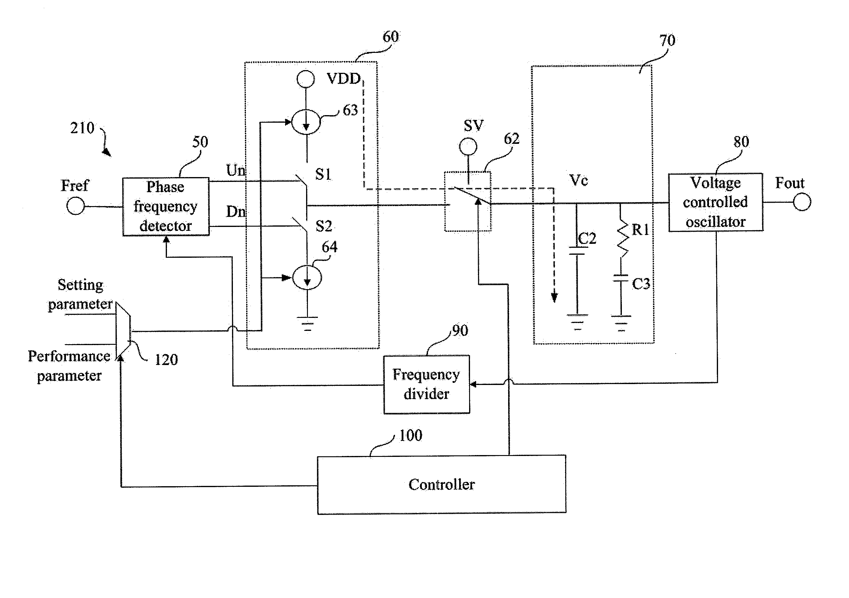
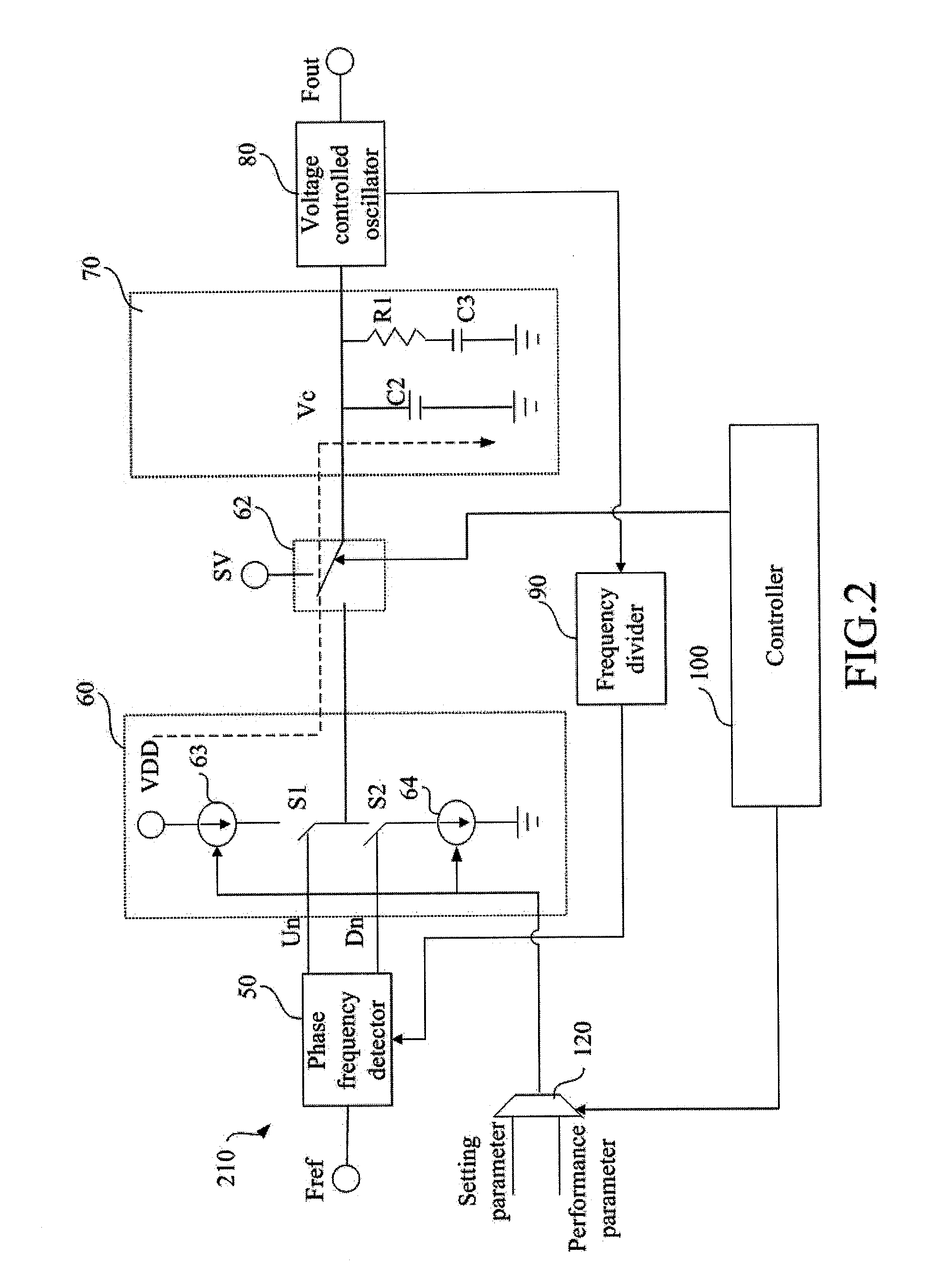
[0023]Please refer to FIG. 2, in which the device of phase-locked loop 210 includes a selector 120, a phase frequency detector 50, a charge pump 60, a switch 62, a low pass filter 70, a voltage controlled oscillator 80, a frequency divider 90, and a controller 100.

[0024]The phase frequency detector 50 is used for receiving a reference clock and a dividing clock to generate a control signal. The charge pump 60 couples to the phase frequency detector 50, and has an adjustable current source controlled by the selector 120. Wherein the charge pump 60 controls current output according to the control signal outputted by the selector 120 and regulates the adjustable current source to output a first current according to a first parameter (S...


PUM


Abstract

Nowadays, electronic product designs are aimed at saving, due to the trend to reduce energy consumption and carbon output. Ethernet technology has also been aimed specifically at saving energy; IEEE P802.3az standard (Energy Efficient Ethernet, EEE), for Ethernet released by Broadcom is one example. The disclosure turns off the phase-locked loop when the network communication stops, effectively saving the energy consumption of the network chip under the EEE standard. In the case of network reconnection, the disclosure turns on the phase-locked loop to start the network communication through adjusting the current of current source and the parameters of a low pass filter to increase the charging speed for the reference voltage generation of the low pass filter. The disclosure then shortens the start-up time to quickly output the standard output frequency and phase of the phase-locked loop.

Description

CROSS-REFERENCES TO RELATED APPLICATIONS[0001]This non-provisional application claims priority under 35 U.S.C. §119(a) on Patent Application No. 100109367 filed in Taiwan, R.O.C. on 2011 Mar. 18, the entire contents of which are hereby incorporated by reference.BACKGROUND[0002]1. Technical Field[0003]The disclosure relates to a phase-locked loop, and more particularly, to a device of phase-locked loop and the method using the same.[0004]2. Related Art[0005]Please refer to FIG. 1, in which phase-locked loop (PLL) is widely used in wire or wireless communication systems. Generally, PLL includes a phase frequency detector 50, a charge pump 60, a low pass filter 70, a voltage-controlled unit 80, and a divider 90. PLL uses a feedback signal to lock the output clock and phase of an output end at the reference clock and phase of an input end in a circuit loop. Consequently, the objective of PLL is to stabilize the output clock and phase, and reduce the variation thereof. PLL had been devel...

Claims


Application Information

Patent Timeline
Patent Type & Authority Applications(United States)
IPC IPC(8): H03L7/10
CPCH03L7/10H03L7/0891
Inventor HUANG, HUI-MIN
Owner REALTEK SEMICON CORP
Why Eureka
Try Eureka