System and Method for Three-Dimensional Geolocation of Emitters Based on Energy Measurements

a technology of energy measurement and system, applied in the direction of direction finders, instruments, measurement devices, etc., can solve the problems of not being able to use the technique in applications, requiring a large number of real-time measurements and/or terrain modeling, and not being very accura

Active Publication Date: 2012-09-20
EXCELIS INC
View PDF10 Cites 210 Cited by
  • Summary
  • Abstract
  • Description
  • Claims
  • Application Information

AI Technical Summary

Benefits of technology

[0006]An embodiment of the present invention pertains to a three-dimensional (3-D) energy-based emitter geolocation technique that determines the geolocation of a radio frequency (RF) emitter based on energy or r

Problems solved by technology

However, this technique may not be very accurate due to multipath fading and shadowing effects that may significantly distort the expected received signal strength (RSS).
However, this improved technique requires a large number of real-t

Method used


Image

  • System and Method for Three-Dimensional Geolocation of Emitters Based on Energy Measurements
  • System and Method for Three-Dimensional Geolocation of Emitters Based on Energy Measurements
  • System and Method for Three-Dimensional Geolocation of Emitters Based on Energy Measurements

Examples


Embodiment Construction

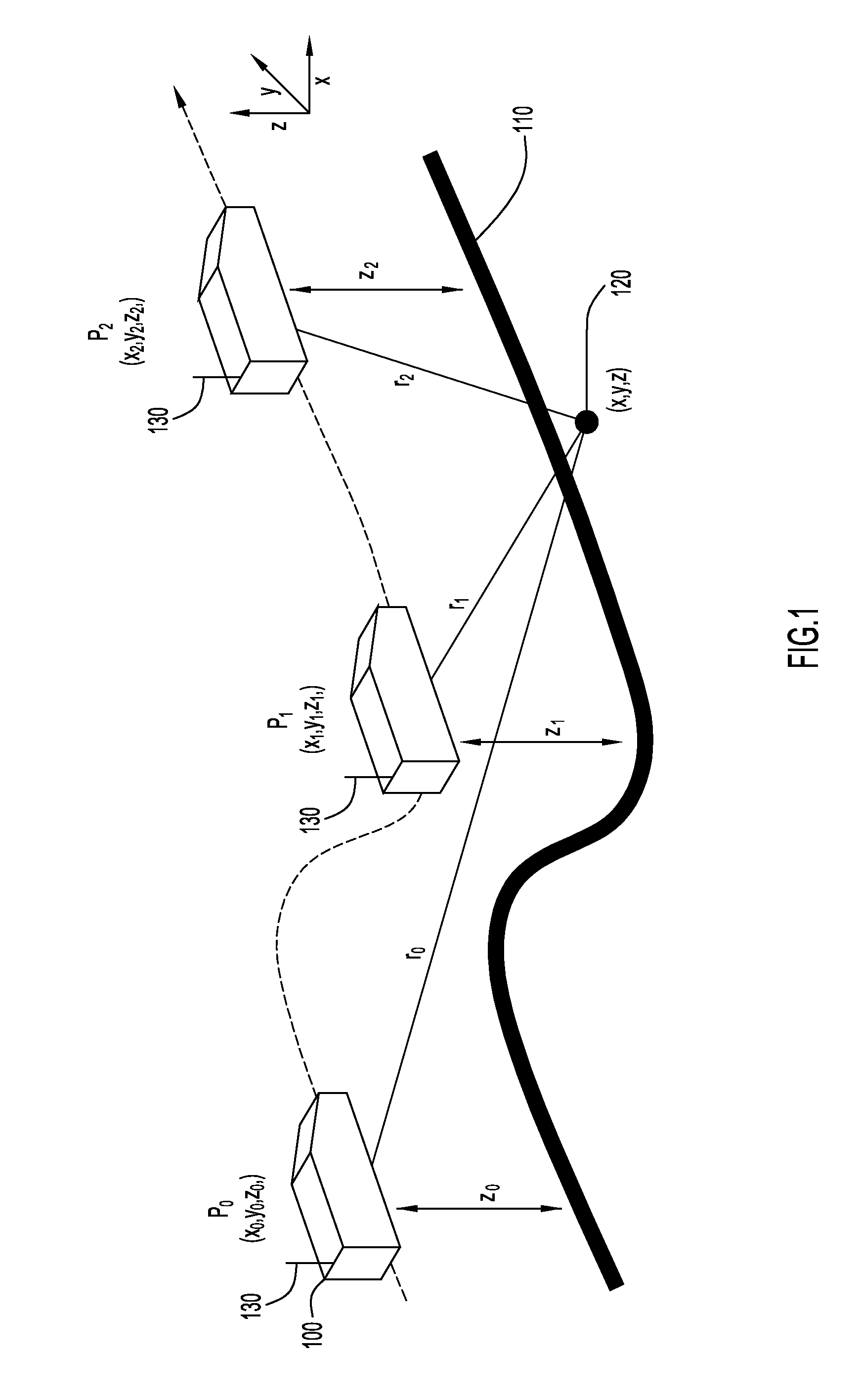
[0014]Embodiments of the present invention pertain to a three-dimensional (3-D) energy-based geolocation technique that obtains reliable geolocation estimates of a radio frequency (RF) emitter based on energy or received signal strength (RSS) of transmitted signals. The geolocation of a radio frequency (RF) emitter is a critical need for many applications. The technique of present invention embodiments may be employed with unmanned air vehicles (UAV) that are usually small, utilized for low altitudes, and employ typical guidance technologies for operation (e.g., following pre-planned or manually provided paths or waypoints). These types of vehicles are well suited for enabling three-dimensional (3-D) geolocation of radio frequency (RF) emitters of interest.

[0015]An example environment for determining the geolocation of a radio frequency (RF) emitter in a three-dimensional space is illustrated in FIG. 1. Specifically, the environment includes a radio frequency (RF) emitter 120, and a...


PUM


Abstract

According to an embodiment of the present invention, a three-dimensional (3-D) energy-based emitter geolocation technique determines the geolocation of a radio frequency (RF) emitter based on energy or received signal strength (RSS) of transmitted signals. The technique may be employed with small unmanned air vehicles (UAV), and obtains reliable geolocation estimates of radio frequency (RF) emitters of interest.

Description

BACKGROUND[0001]1. Technical Field[0002]The present invention embodiments pertain to determining locations of emitters. In particular, the present invention embodiments pertain to determining locations of radio frequency (RF) emitters in a three-dimensional space based on energy or received signal strength (RSS) measurements of the emitters at various locations.[0003]2. Discussion of Related Art[0004]Conventional techniques for geolocation of a radio frequency (RF) emitter are commonly based on measurements of a received signal strength (RSS) of signals transmitted from the emitter. Accordingly, this RSS-based technique may also be referred to as an energy-based technique. The received signal strength (RSS) is usually integrated over the duration of the transmitted signal in order to obtain a signal energy measurement and enhance signal to noise ratio. Since the transmitted radio frequency (RF) signal attenuates during propagation through space, the received signal strength (RSS) of...

Claims


Application Information

Patent Timeline
IPC IPC(8): G01S5/02
CPCG01S5/0242G01S5/0289G01S11/06G01S5/0249
Inventor LU, NING HSING
Owner EXCELIS INC
Why Eureka
Try Eureka