
Discharge testing device

Inactive Publication Date: 2012-09-20
SEIKO EPSON CORP
View PDF3 Cites 6 Cited by
  • Summary
  • Abstract
  • Description
  • Claims
  • Application Information

AI Technical Summary

Benefits of technology

[0007]An advantage of some aspects of the invention is that it provides a discharge testing device determining whether a liquid droplet is discharged normally within a short time.
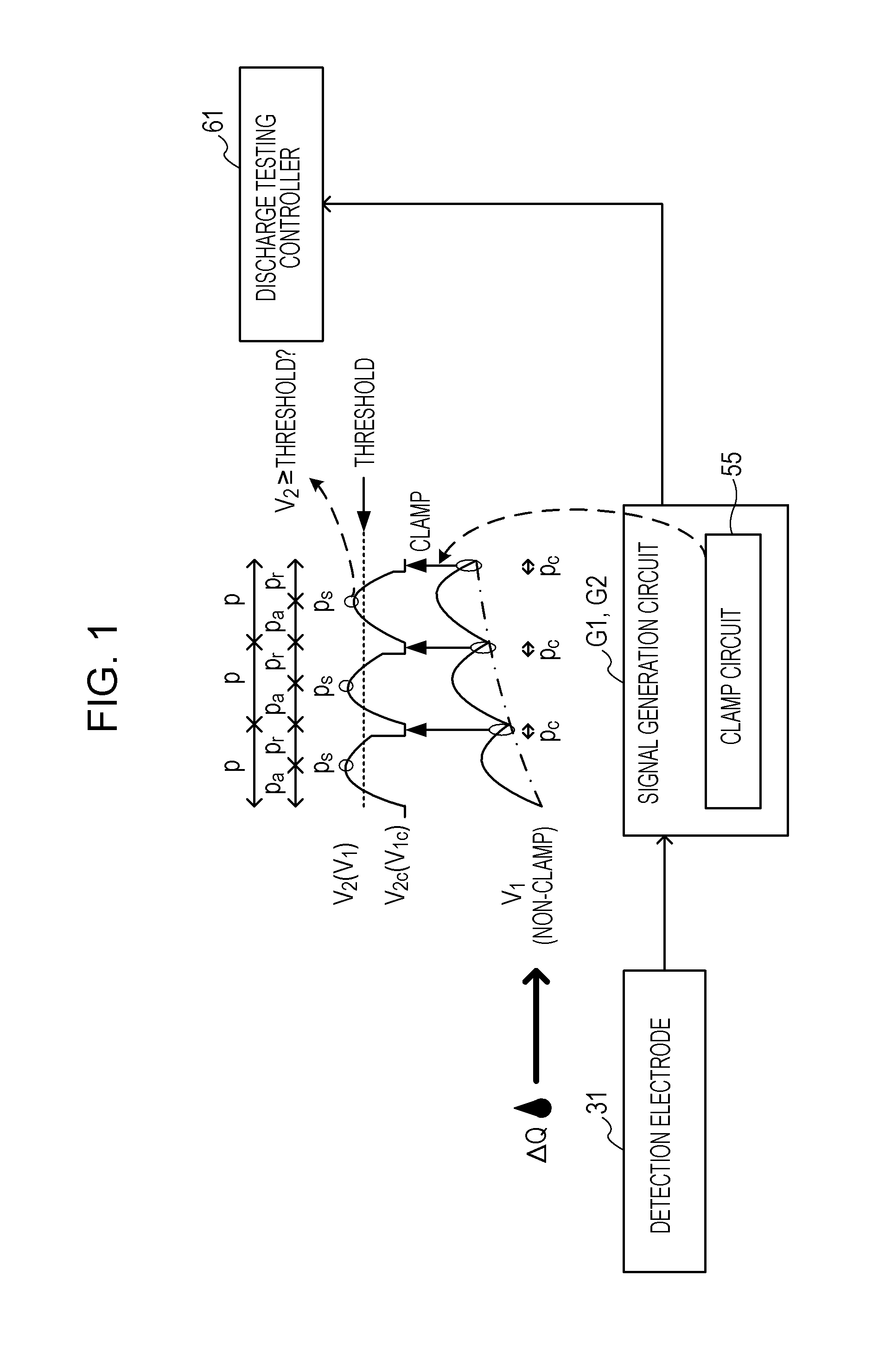
[0008]According to an aspect of the invention, there is provided a discharge testing device. In the discharge testing device, a discharge controller discharges a liquid droplet from a nozzle such that a discharge testing period including a discharge period in which a liquid droplet is discharged from a nozzle and a non-discharge period in which the liquid droplet is not discharged from the nozzle is repeated. A detection signal acquiring unit acquires a detection signal whose signal strength varies in response to a liquid droplet discharged from a nozzle during the discharge period. A low-pass filter eliminates a high frequency component from a detection signal, and a first amplifier amplifies a detection signal and generates a first amplification signal. Further, a restricting unit restricts the signal strength of a first amplification signal to predetermined strength during a restriction period included in the discharge testing period. A second amplifier amplifies a first amplification signal to generate a second amplification signal. A determinator determinates whether a liquid droplet is normally discharged from a nozzle based on the signal strength of a second amplification signal during a sampling period after a predetermined time elapses from the restriction period.
[0009]Since the restriction period is included in the discharge testing period, the signal strength of a first amplification signal having a period equal to or shorter than the discharge testing period is restricted to predetermined strength. In so doing, a noise component in the signal strength is prevented from being accumulated through a plurality of discharge testing periods. Accordingly, influence of a low frequency noise component superimposed on the first amplification signal may be suppressed. Further, it may be compared with a case of suppressing a low frequency noise component using a high-pass filter to prevent waveform distortion and delay of the detection signal, and the time period required to the discharge of a liquid droplet from a nozzle to the performance of the determination process by the determinator may be reduced. Accordingly, by repeating a large number of discharge testing periods, the time period required for performing discharge testing for a plurality of nozzles may be reduced. On the other hand, because a low-pass filter eliminates a high frequency component from a detection signal, it may suppress the influence of a high frequency noise component superimposed on the first amplification signal. Accordingly, a determination result having high noise resistance may be obtained. Furthermore, since a second amplifier is provided in addition to the first amplifier, although the amplification rate in the first amplifier is suppressed, it may be supplemented by the second amplifier. Accordingly, this may prevent the first amplification signal from exceeding an output possible range of the first amplifier, distortion of a signal wave due to clipping may be prevented, and deterioration of determination precision due to distortion of the signal wave may be prevented.
[0011]In addition, a secondary restricting unit restricting signal strength of a first amplification signal during a secondary restriction period after a sampling time instead thereof during a discharge testing period may be included. Moreover, the determinator may determine whether a liquid droplet is normally discharged in consideration of signal strength of the second amplification signal in a secondary sampling time after a predetermined time elapses from the secondary restriction period. That is, during a single discharge testing period, two sets of convergence and sampling are provided, so that determination may be made in consideration of signal strength of a second amplification signal in two sampling times, and reliance of the determination may be improved. Because restriction is performed to reduce the influence of low frequency noise with suppression of delay in the detection signal, although a set of restriction and sampling is provided twice, the time required for discharge testing being lengthened may be prevented.
[0012]A restricting unit restricts signal strength of a first amplification signal with predetermined strength, but a switch switching to the predetermined strength in a plurality of strengths may be provided. Here, the signal strength of the first amplification signal is restricted to a predetermined strength and is changed based on a predetermined strength. Accordingly, the restricting unit switches a predetermined strength restricting signal strength of the first amplification signal, and a strength band whose signal strength of the first amplification signal varies may be adjusted. That is, when noise is included in a signal strength of the first amplification signal, the strength signal is switched such that a signal strength of the first amplification signal may be changed to the strength band in which the signal strength of the first amplification signal have no problems. For example, signal strength of the first amplification signal does not exceed an output allowable range, and waveform distortion may be prevented due to clamp of the first amplification signal.
[0013]Further, the discharge testing device may further includes a plurality of signal generators that include a detection signal acquiring unit, a low-pass filter, a first amplifier, a restricting unit, and a second amplifier, and the detection signal acquiring units may acquire a detection signal whose signal strength varies in response to liquid droplets discharged from different nozzles, respectively. In doing so, discharge testing for different nozzles may be performed in a parallel way, and the period required to perform discharge testing for a plurality of nozzles may be reduced.

Problems solved by technology

However, a band-pass (bypass) filter has a problem in that a signal wave of a voltage signal caused by the liquid droplet landed on the vibration plate is distorted or delayed.
In particular, there is a problem in that a time period required to test clogging of a nozzle is extended due to the occurrence of a delay in the signal wave of the voltage signal.
Further, in Japanese Patent No. 4501461, since there is also a need to await the mechanical vibration of the vibration plate itself returning to normal, a problem arises in that the period required for testing is easily lengthened.

Method used


Image

  • Discharge testing device
  • Discharge testing device
  • Discharge testing device

Examples


first embodiment

2. FIRST EMBODIMENT

2-1. Configuration of Discharge Testing Device

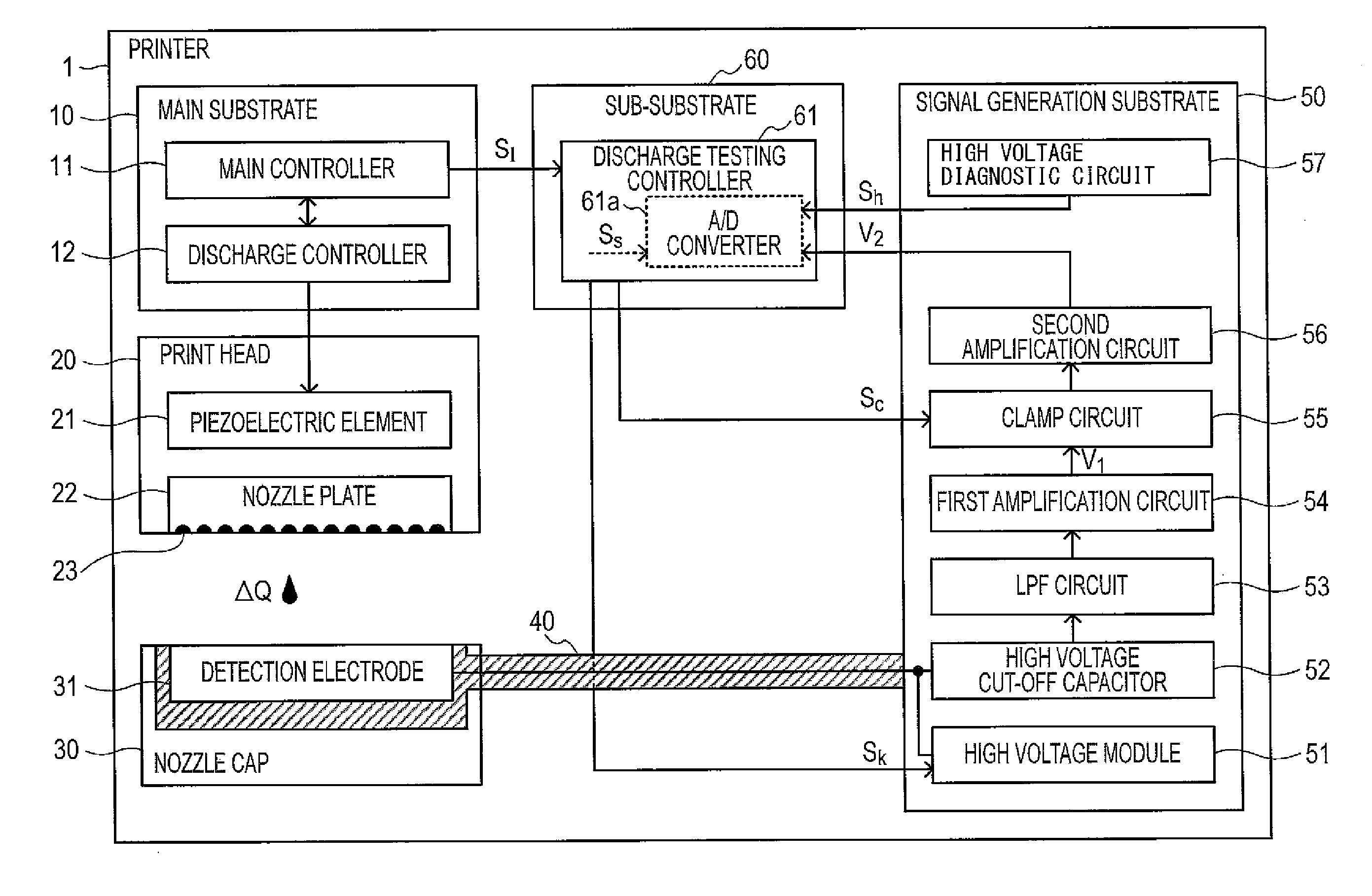
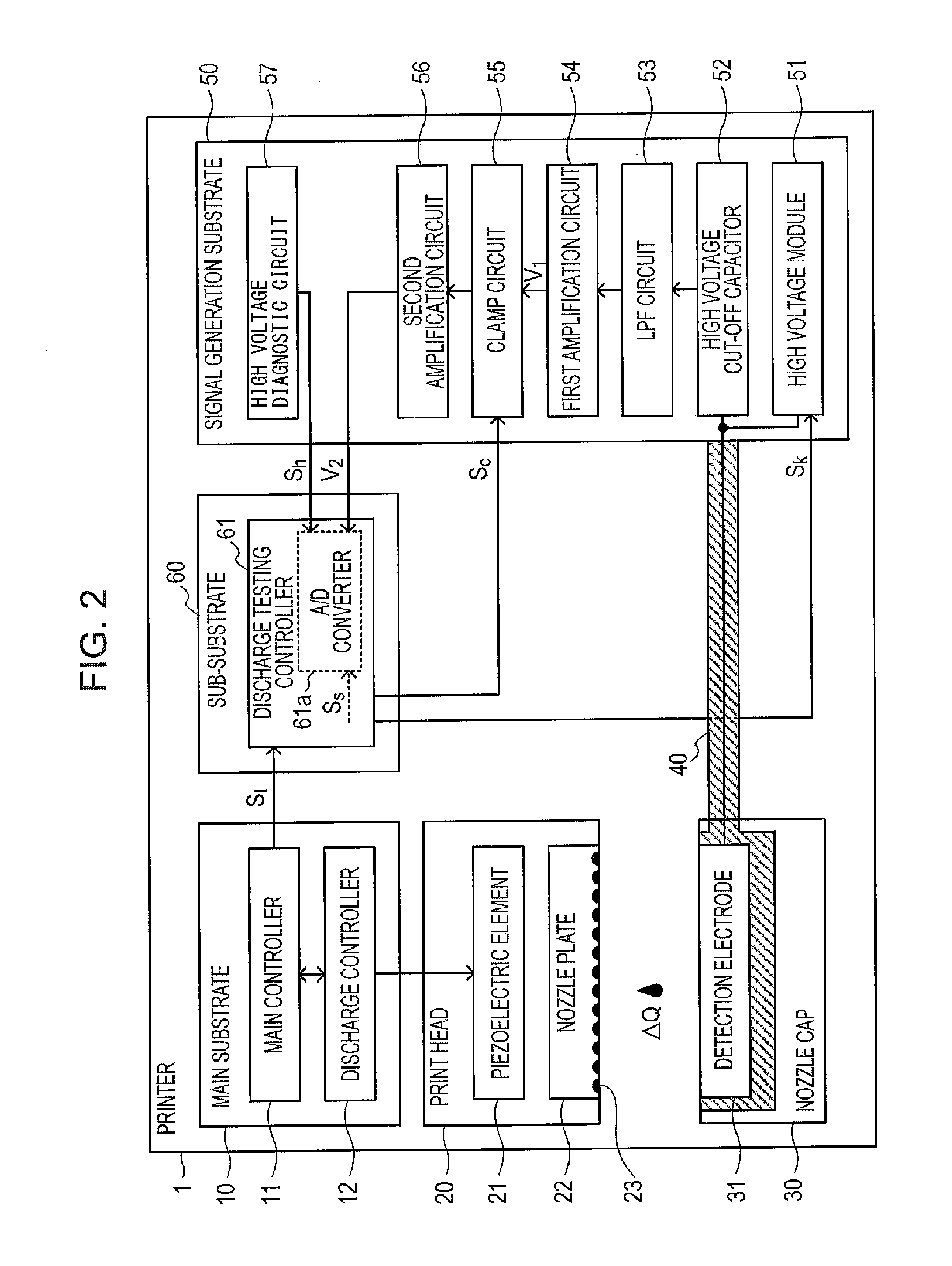
[0027]FIG. 2 is a block diagram illustrating a printer 1 including a discharge testing device according to a first embodiment. The printer 1 includes a main substrate 10, a print head 20, a nozzle cap 30, a shield structure 40, a signal generation substrate 50, and a sub-substrate 60. A printer 1 of a first embodiment is an ink-jet printer. The main substrate 10 includes a main controller 11 and a discharge controller 12. The main controller 11 is configured by a CPU, a RAM, a ROM, an ASIC, and the like, and performs a process that generates printing data based on image data acquired through an interface unit (not shown), and outputs corresponding printing data to the discharge controller 12. Further, the main controller 11 performs a process that notifies the result of discharge testing to be described later through a user interface unit (not shown). The discharge controller 12 includes a CPU, a RAM, a ROM, an ASIC, a...

second embodiment

3. SECOND EMBODIMENT

[0058]FIG. 7 is a block diagram illustrating main parts of a discharge testing device according to a second embodiment. Here, only matters differing from those of the first embodiment will be described in the second embodiment. In the second embodiment, two clamp circuits 551 and 552 are provided. The clamp circuit 552 corresponds to a second clamp circuit. The clamp circuit 551 inputs a predetermined electric potential V1c1 (=0V) to a clamp point CP1 of a coupling capacitor C3 side, and the clamp circuit 552 inputs a predetermined electric potential V1c1 (=0.6V) to a clamp point CP2 of a second amplification circuit 56 side. Clamp signals Sc1, and Sc2 are input to the clamp circuits 551 and 552 through separate wires from a discharge controller 61 of a sub-substrate 60, respectively.

[0059]FIG. 8 is a timing chart of a discharge testing according to a second embodiment. (d1) and (d2) of FIG. 8 illustrate clamp signals Sc1 and Sc2 input to the clamp circuits 551 a...


PUM


Abstract

A discharge testing device comprising:a discharge controller discharging a liquid droplet from a nozzle such that a discharge testing period including a discharge period; a detection signal acquiring unit acquiring a detection signal; a low-pass filter eliminating a high frequency component from the detection signal; a first amplifier amplifying the detection signal to generate a first amplification signal; a restricting unit restricting signal strength of the first amplification signal during a restriction period included in the discharge testing period to predetermined strength; a second amplifier amplifying the first amplification signal to generate a second amplification signal; and a determinator determining whether a liquid droplet is normally discharged based on signal strength based on signal strength of a second amplification signal during a sampling period after a predetermined time elapses from the restriction period.

Description

CROSS-REFERENCE TO RELATED APPLICATIONS[0001]This application claims priority to Japanese Patent Application No. 2011-060486 filed on Mar. 18, 2011. The entire disclosure of Japanese Patent Application No. 2011-060486 is hereby incorporated herein by reference.BACKGROUND[0002]1. Technical Field[0003]The present invention relates to a discharge testing device for determining whether a liquid droplet is discharged normally.[0004]2. Related Art[0005]A liquid discharge device has been proposed which includes a vibration plate on which a liquid droplet discharged from a nozzle is landed and determines clogging of a nozzle based on a voltage signal changed by mechanically vibrating the vibration plate (refer to Japanese Patent No. 4501461). The liquid discharge device extracts, through a band-pass filter, a signal component of a frequency band caused by a liquid droplet landed on a vibration plate, and determines that a nozzle is clogged when the signal component is smaller than a predete...

Claims


Application Information

Patent Timeline
IPC IPC(8): B41J29/393
CPCB41J2/16579
Inventor NAKAZAWA, YOSHIO
Owner SEIKO EPSON CORP
Learn More