

Screw expander system
a screw expander and expander technology, applied in the direction of machines/engines, rotary/oscillating piston pump components, liquid fuel engines, etc., can solve the problem of increasing the size of the screw expander system b>100/b>, and achieve the reduction of the size of the device, the suppression of the leakage of the operating medium, and the reduction of the loss of mechanical power
- Summary
- Abstract
- Description
- Claims
- Application Information
AI Technical Summary
Benefits of technology
Problems solved by technology
Method used
Image

Examples
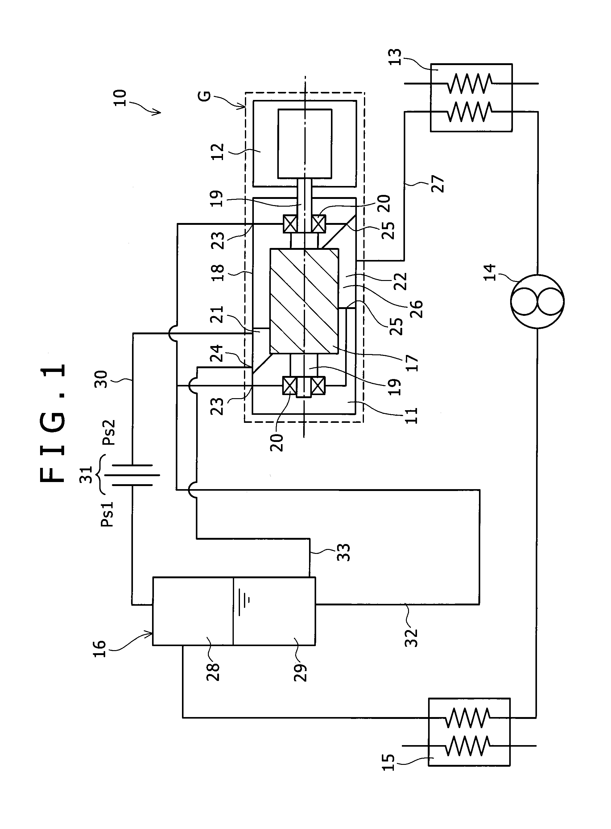
first embodiment
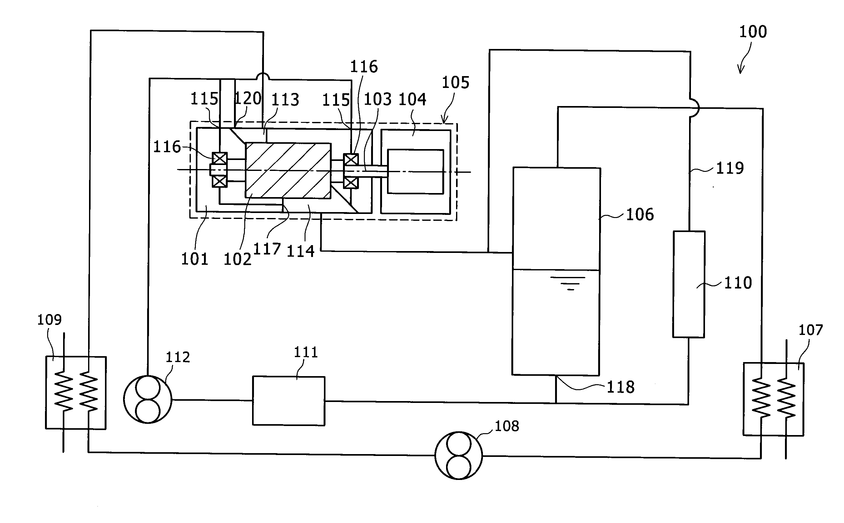
[0024]FIG. 1 shows a screw expander system 10 of the present invention. This screw expander system 10 includes a screw expander 11, a condenser 13, a pump 14, an evaporator 15, and an oil separating tank 16.
[0025]The screw expander 11 includes a pair of male and female screw rotors 17 meshed with each other. FIG. 1 only shows the screw rotor 17 connected to a generator 12 among the pair of male and female screw rotors 17 rotatably contained inside a casing 18. Rotor shafts 19 extending on both sides in the rotation shaft direction are provided in the screw rotor 17. The rotor shaft 19 on the side of the generator 12 penetrates a surface of the casing 18 on the side of the generator 12 and protrudes to the outside. The rotor shafts 19, 19 on both the sides of the screw rotor 17 are respectively supported by bearings 20, 20. In the screw expander 11, an expansion space for expanding an operating medium is formed by the pair of male and female screw rotors 17 and the casing 18 containi...
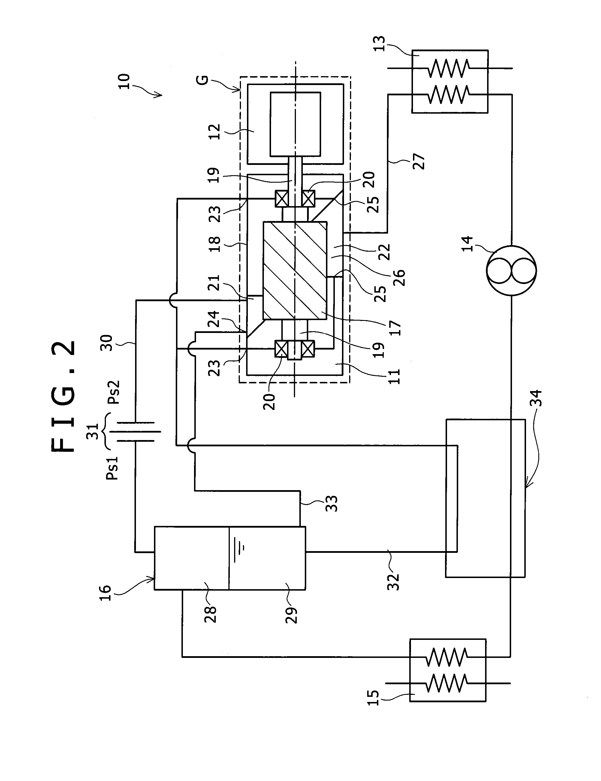
second embodiment
[0048]In the present embodiment, the heat exchanger 34 is provided as well as the The condenser 13 is an air-cooled type condenser.
[0049]The mixture containing the gas (vapor) and the liquid (hot water) jetted from the production well is separated into the gas and the liquid in the gas-liquid separator 37. The gas is contained in the gas containing section 38, and the liquid is contained in the liquid containing section 39. The gas from the gas containing section 38 of the gas-liquid separator 37 is sent to the evaporator 15, and the mixture pressure-fed by the pump 14 is evaporated by exchanging heat with the gas by the evaporator 15. The gas, the liquid, or the gas-liquid mixture from the evaporator 15, and the liquid from the liquid containing section 39 of the gas-liquid separator 37 are merged and fed to the preheater 36, heat is exchanged between the liquid or the gas-liquid mixture merged in the preheater 36, and the mixture pressure-fed by the pump 14, and then the gas-liqu...
PUM
 Abstract
Description
Claims
Application Information