Apparatus and method for accessing an intrapericardial space

a technology of intrapericardial space and apparatus, applied in the field of medical equipment and methods, can solve the problems of increasing the risk of tamponade, difficulty in accessing the intrapericardial space, and puncture of the heart wall,

Active Publication Date: 2012-09-20
PACESETTER INC
View PDF4 Cites 23 Cited by
  • Summary
  • Abstract
  • Description
  • Claims
  • Application Information

AI Technical Summary

Problems solved by technology

However, for the patients with a normal pericardial sac and no extra fluid between the pericardial sac and the heart wall, gaining access into the intrapericardial space is difficult.
This difficultly arises because: the normal pericardial sac is a thin tough connective tissue with little stretchability; the pericardial sac is slippery on, and slides over, the heart wall; and the “virtual space” that is available for puncture provides doctors with little puncture room for pressing the needle into the pericardial sac.
The challenges of accessing an intra

Method used


Image

  • Apparatus and method for accessing an intrapericardial space
  • Apparatus and method for accessing an intrapericardial space
  • Apparatus and method for accessing an intrapericardial space

Examples


first embodiment

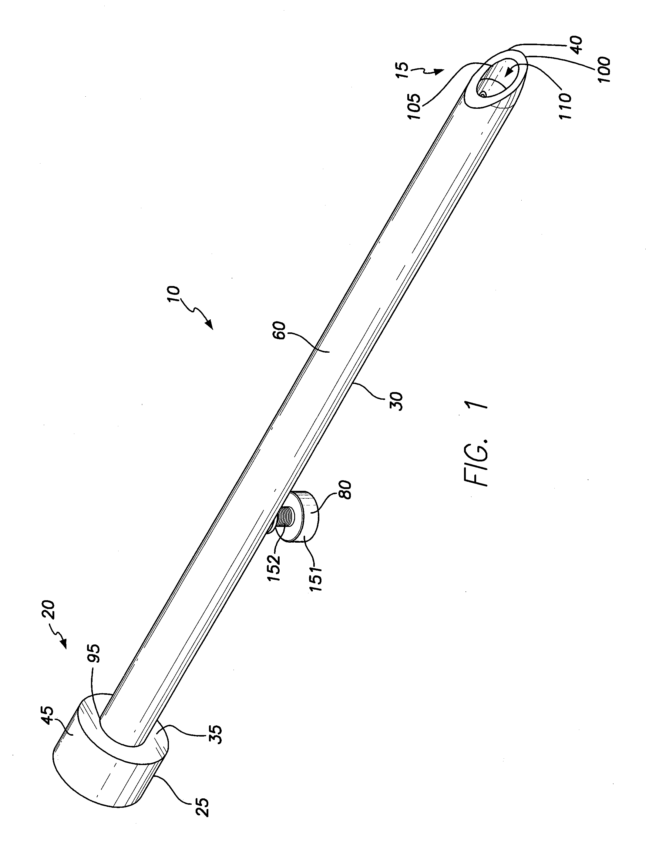
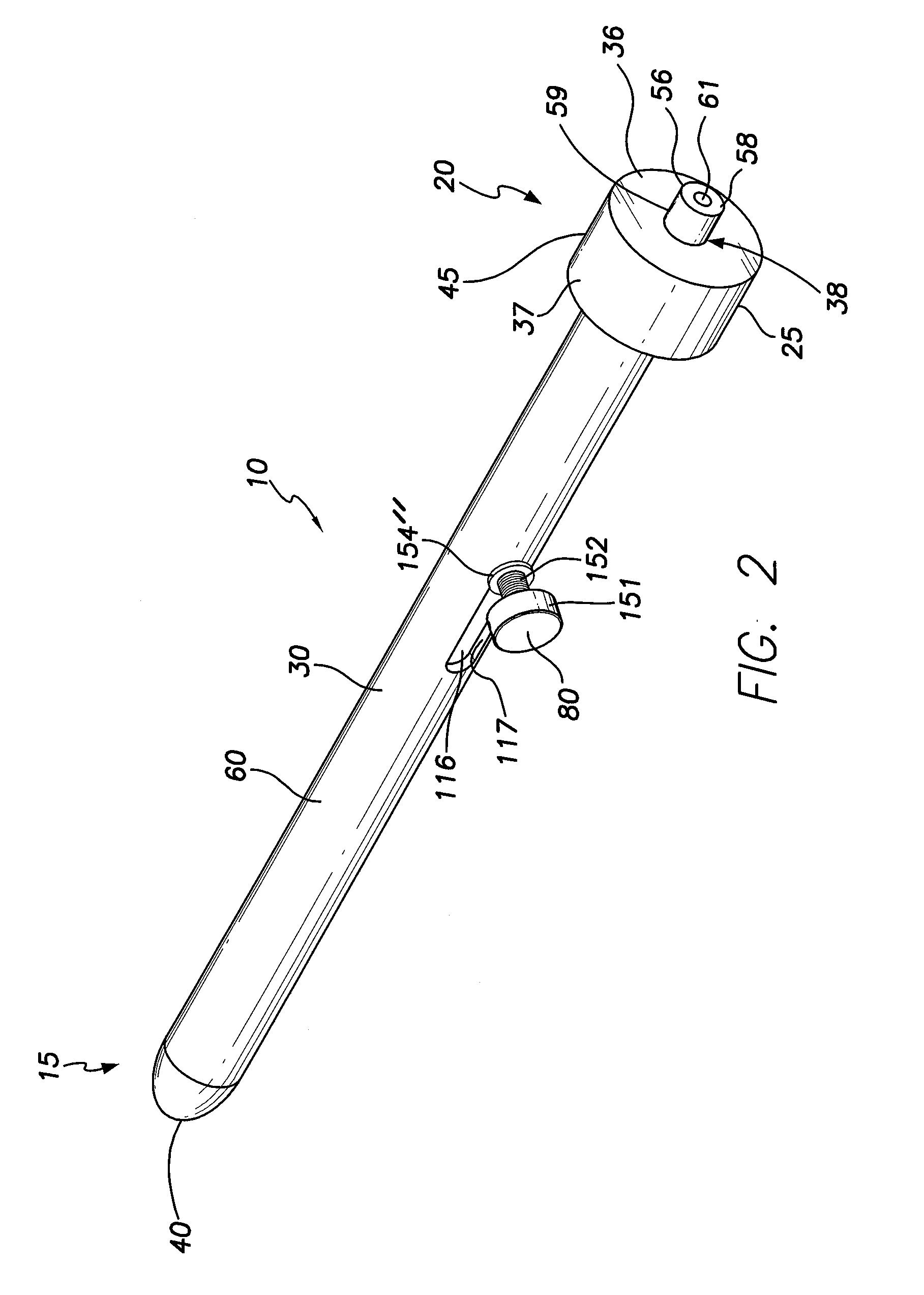
[0027]For a detailed discussion of the device 10, reference is made to FIGS. 1 and 2, which are isometric views of the device 10 oppositely viewed. As shown in FIGS. 1 and 2, the device 10 includes a distal end 15 and a proximal end 20 opposite the distal end. A handle 25 is at the proximal end, and a tubular body assembly 30 extends distally from a distal face 35 of the handle to a distal tip 40 of the tubular body assembly 30 at the distal end 15. The handle includes a proximal face 36 and a cylindrical outer circumferential surface 37 extending between the proximal and distal faces 35, 36.

[0028]As illustrated in FIG. 3, which is the same view as FIG. 1, except the device 10 is exploded, the handle 25 of the device 10 includes an outer handle portion 45, a needle deployment button 56, and a helical spring 55 that biases the button 56 proximally relative to the outer handle portion 45. The outer handle portion 45 includes a large diameter cylindrical portion 46 and a small diameter...

second embodiment

[0055]As shown in FIG. 17, which is the same view as FIG. 5, except of the device 10, the device is generally the same as described above, except the device 10 has a spring loaded inner tubular body 65 and a pinching member 300 separately operated from the spring knob 85. Specifically, the device 10 is a needle spring holder including the helical tissue spring 85 as described above with respect to FIGS. 1-8, a latching or pinching member 300, the spring control knob 80 as described above with respect to FIGS. 1-8, and the inner tubular body 65 as described above, except configured for a spring-loaded release. The pinching member 300 is part of a pinching member assembly 302 that includes the pinching member 300 and an actuation lever 304 pivotally coupled to the outer tubular body at a proximal end 306 of the pinching member 300. The pinching member 300 is located in the lumen 110 of the outer tubular body 60 and is a longitudinally extending member that runs generally parallel to t...

third embodiment

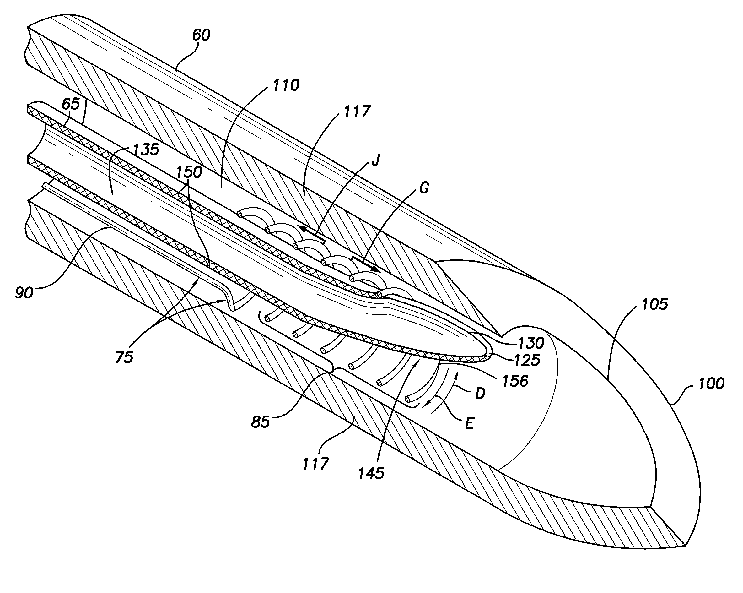
[0059]As can be understood from FIGS. 19, 20 and 21, which are respectively the same as FIGS. 3, 6 and 7, except of the device 10, the pinching member 300 is part of the engagement spring assembly 70 and acts with the helical tissue engagement spring 85 to pinch a pericardial sac 208. Specifically, as shown in FIG. 19, the pinching member 300, also referred to as a longitudinally extending member, has a proximal end 306 coupled to the knob 80 and a blunt distal end 308 near the distal end of the outer tubular body 60. The member 300 extends generally parallel to the straight portion 90 of the spring 75 extending between the knob 80 and the helical portion 85.

[0060]As shown in FIG. 20, the configuration and aspects of the spring assembly 70 are generally the same as described above with respect to FIG. 1-8, except the proximal end 306 of the member 300 is pivotally coupled about a bearing surface 312 on the free end 153 of the knob 80. As a result, the knob can be rotated as depicted...


PUM


Abstract

A medical device is disclosed herein that is configured to engage and penetrate a pericardial sac. The device includes an outer tubular body, an inner tubular body, and a helical tissue engagement member. The outer tubular body includes a proximal end, a distal end and a lumen extending between the ends. The inner tubular body includes a proximal end and a distal end. The inner tubular body is located in the lumen of the outer tubular body. The proximal end of the inner tubular body is operably coupled to the proximal end of the outer tubular body. The distal end of the inner tubular body is extendable out of the distal end of the outer tubular body. The helical tissue engagement member is displaceable from a first position to a second position, the first position being in the lumen of the outer tubular body recessed relative to the distal end of the outer tubular body, and the second position extending out of the distal end of the outer tubular body. The helical tissue engagement member is also rotatable relative to the outer tubular body.

Description

FIELD OF THE INVENTION[0001]The present invention relates to medical apparatus and methods. More specifically, the present invention relates to apparatus for, and methods of, accessing an intrapericardial space.BACKGROUND OF THE INVENTION[0002]To gain percutaneous access into the intrapericardial space (i.e., the space between the pericardial sac and the heart wall), doctors use a sub-xiphoid puncture technique employing a 17-gauge Touhy needle. Doctors use fluoroscopic guidance to visualize the needle placement with respect to the heart. Contrast media is also used during puncture to determine if the needle has passed through the pericardial sac and is correctly located in the intrapericardial space.[0003]For patients with pericarditis, fluid raises the pericardial sac away form the heart wall, thereby making puncture easier to achieve. However, for the patients with a normal pericardial sac and no extra fluid between the pericardial sac and the heart wall, gaining access into the ...

Claims


Application Information

Patent Timeline
IPC IPC(8): A61M5/32
CPCA61M5/3286A61B17/0218A61B2017/00349A61B2017/3488A61B17/3478A61B2017/00243A61B2017/00247A61B2017/0237
Inventor TOY, STEPHANIETAO, JOYCEWONG, VIVIAN
Owner PACESETTER INC
Why Eureka
Try Eureka