Pluggable mechanism, production board and subrack having the pluggable mechanism

a production board and pluggable technology, applied in the direction of gearing, couplings, hoisting equipments, etc., can solve the problems of large motion resistance, multi-step drive, complex structure, etc., and achieve the effect of small motion resistance, high operation reliability and simple structur

Active Publication Date: 2012-09-27
HUAWEI TECH CO LTD
View PDF8 Cites 14 Cited by
  • Summary
  • Abstract
  • Description
  • Claims
  • Application Information

AI Technical Summary

Benefits of technology

[0007]Embodiments of the present invention provide a pluggable mechanism, and a production board and subrack having the pluggable mechanism. The pluggable mechanism has a simple structure, high reliability, good operability, no occupation of vertical space, and small motion resistance, and is suitable for board plugging requiring great force for inserting and removing.
[0011]The pluggable mechanism according to the above solutions has an obvious effect as compared with the conventional structure: With the pluggable mechanism, production board, and subrack provided by embodiments of the present invention, the pluggable mechanism has a simple structure and high operation reliability; the pluggable mechanism is disposed between the bearing board and a to-be-inserted board and does not occupy vertical space; the torque applied on the handle of the gear wrench directly drives the swing gear to swing upward and downward on the back swing plane; the pluggable mechanism has small motion resistance and good operability, and is suitable for board plugging requiring many connectors and great force for inserting and removing.

Problems solved by technology

1. Complex structure, multi-step drive, and insufficient operation reliability.
2. Occupation of vertical space.
3. Great motion resistance, laborious operation, and poor operability, especially unsuitable for the PCB board plugging requiring great force for inserting or removing.

Method used


Image

  • Pluggable mechanism, production board and subrack having the pluggable mechanism
  • Pluggable mechanism, production board and subrack having the pluggable mechanism
  • Pluggable mechanism, production board and subrack having the pluggable mechanism

Examples


embodiment 1

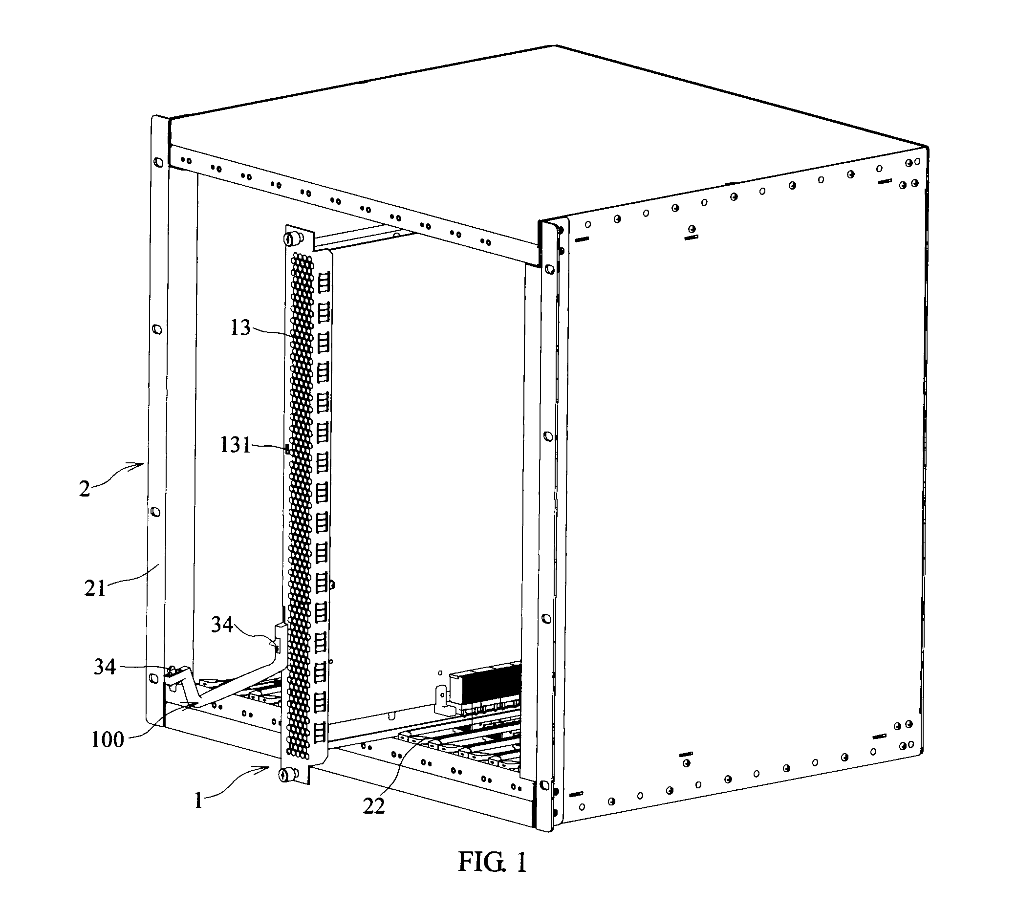
[0022]As shown in FIG. 1, the embodiment of the present invention provides a pluggable mechanism 100, and a production board 1 having the pluggable mechanism 100 and a subrack 2 having the pluggable mechanism 100.

[0023]The subrack 2 includes a housing 21 and the production board 1 that is inserted into the housing 21 by sliding. If a backplane is disposed at the bottom of the housing 21, the subrack 2 can form a direct front-to-back air duct, so as to achieve good heat dissipation effect. In this state, the production board 1 needs to be in a vertical position to plug in the backplane. A guide rail 22 is disposed at the bottom of the housing 21, and the bottom of the production board 1 is inserted into the guide rail 22 by sliding, while the backplane is disposed below the guide rail 22.

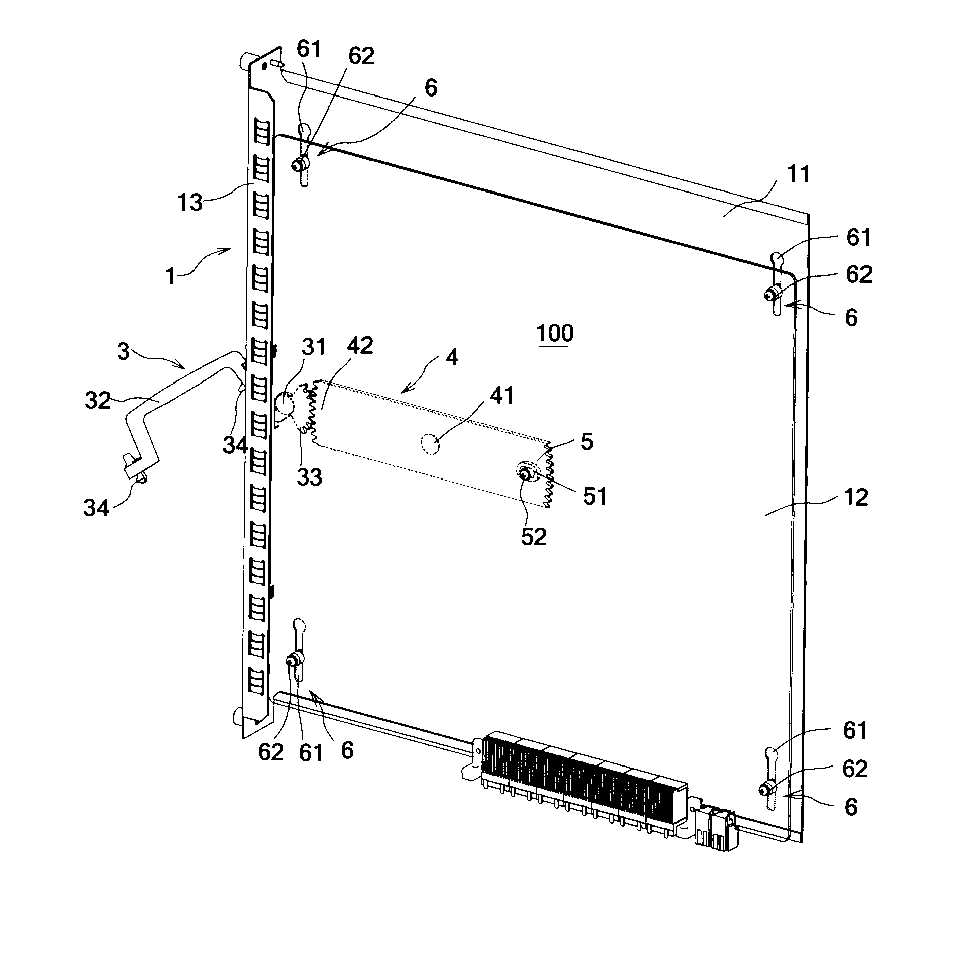
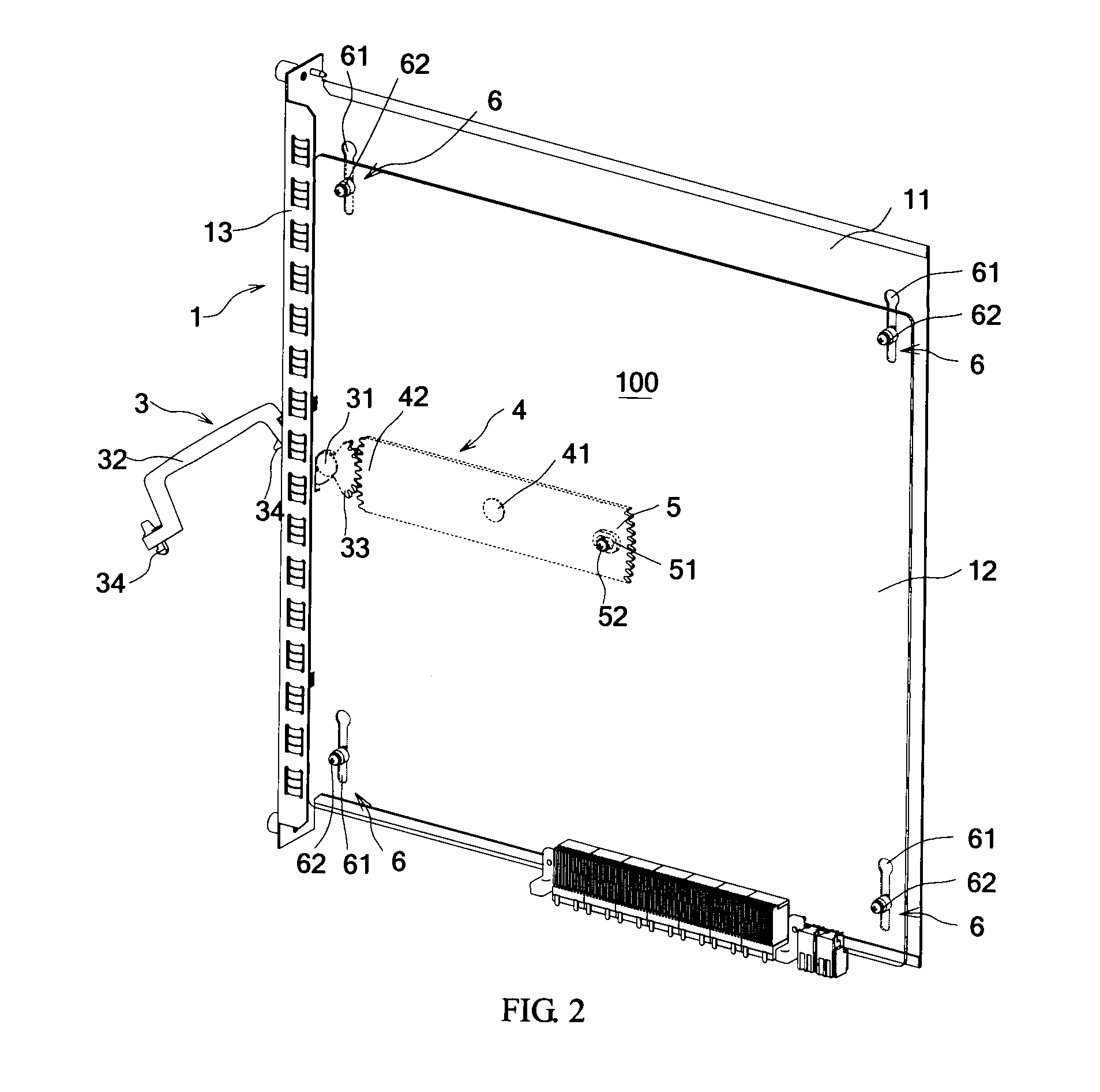
[0024]As shown in FIGS. 2 and 3, the production board 1 includes a bearing board 11, a to-be-inserted board 12 (for example PCB boards such as a PCI card), and a pluggable mechanism 100 located betwe...

embodiment 2

[0035]As shown in FIG. 6, the embodiment of the present invention provides a pluggable mechanism 100, and a production board 1 and subrack 2 having the pluggable mechanism 100. Main structures, principles, and effects are the same as those of the first embodiment and are not described herein. For clarity and brevity, FIG. 6 does not illustrate the complete production board 1 and subrack 2, and only shows the difference, where the to-be-inserted board 12 in the production board 1 is already removed to make the pluggable mechanism 100 visible. The difference between this embodiment and the first embodiment is that the horizontal guide rail 51 of the linking structure 5 is disposed on the to-be-inserted board 12, while the linking pin 52 is disposed on the swing gear 4.

embodiment 3

[0036]As shown in FIG. 7, the embodiment of the present invention provides a pluggable mechanism 100, and a production board 1 and subrack 2 having the pluggable mechanism 100. Main structures, principles, and effects are the same as those of the first embodiment and are not described herein. For clarity and brevity, FIG. 7 only illustrates the production board 1 and does not illustrate the subrack 2. The linking structure in this embodiment is the same as that in the first embodiment. The horizontal guide rail 51 is disposed on the swing gear 4, and the linking pin 52 is disposed on the back of the to-be-inserted board 12. The difference is as follows:

[0037]The pluggable mechanism 100 includes one gear wrench 3 and two swing gears 4; the gearing tooth part 42 of the swing gear 4 and the linking structure 5 are located on the same side of the hinging point of the pivot hinge 41 of the swing gear 4; a transitional tooth part 43 is disposed at the other end of the swing gear 4 where n...


PUM


Abstract

A pluggable mechanism, disposed between a bearing board and a to-be-inserted board, includes: a gear wrench hinged on the bearing board, where the gear wrench comprises a handle and a drive tooth part; and a swing gear, hinged on the bearing board and connected to the to-be-inserted board, where the swing gear comprises a gearing tooth part meshing with the drive tooth part, and the to-be-inserted board moves with the move of the swing gear. A production board including the above pluggable mechanism is also disclosed. A subrack including the above production board is also disclosed. The pluggable mechanism has a simple structure, high reliability, good operability, no occupation of vertical space, and small motion resistance, and is suitable for board plugging requiring great force for inserting and removing.

Description

CROSS-REFERENCE TO RELATED APPLICATIONS[0001]This application is a continuation of International Application No. PCT / CN2011 / 073627, filed on May 4, 2011, which claims priority to Chinese Patent Application No. 201010213955.7, filed on Jun. 28, 2010, both of which are hereby incorporated by reference in their entireties.FIELD OF THE INVENTION[0002]The present invention relates to a motion mechanism, and in particular, to a pluggable mechanism, and a production board and subrack having the pluggable mechanism.BACKGROUND OF THE INVENTION[0003]In a conventional device, a backplane is horizontally disposed at the bottom of a subrack, and a PCB board is vertically inserted from the front of the subrack into the subrack and then moved downward to fit into the backplane. In this way, the resistance and restraint from the backplane on the back side of the subrack can be eliminated, a direct front-to-back air duct is formed in the subrack, and heat dissipation is implemented through the front...

Claims


Application Information

Patent Timeline
Patent Type & Authority Applications(United States)
IPC IPC(8): F16H19/00
CPCY10T74/19642H05K7/1409
Inventor LI, SHUANGZHAO, JUNLI, YAO
Owner HUAWEI TECH CO LTD
Why Eureka
Try Eureka