

Air pollution control system and air pollution control method, spray drying device of dewatering filtration fluid from desulfurization discharged water, and method thereof
a technology of desulfurization and air pollution control, which is applied in the direction of liquid degasification, lighting and heating apparatus, and separation processes, etc., can solve the problems of complex desulfurization discharged water and high treatment cost, and achieve stable atomization, reduce the effect of the deposi
- Summary
- Abstract
- Description
- Claims
- Application Information
AI Technical Summary
Benefits of technology
Problems solved by technology
Method used
Image

Examples
first embodiment
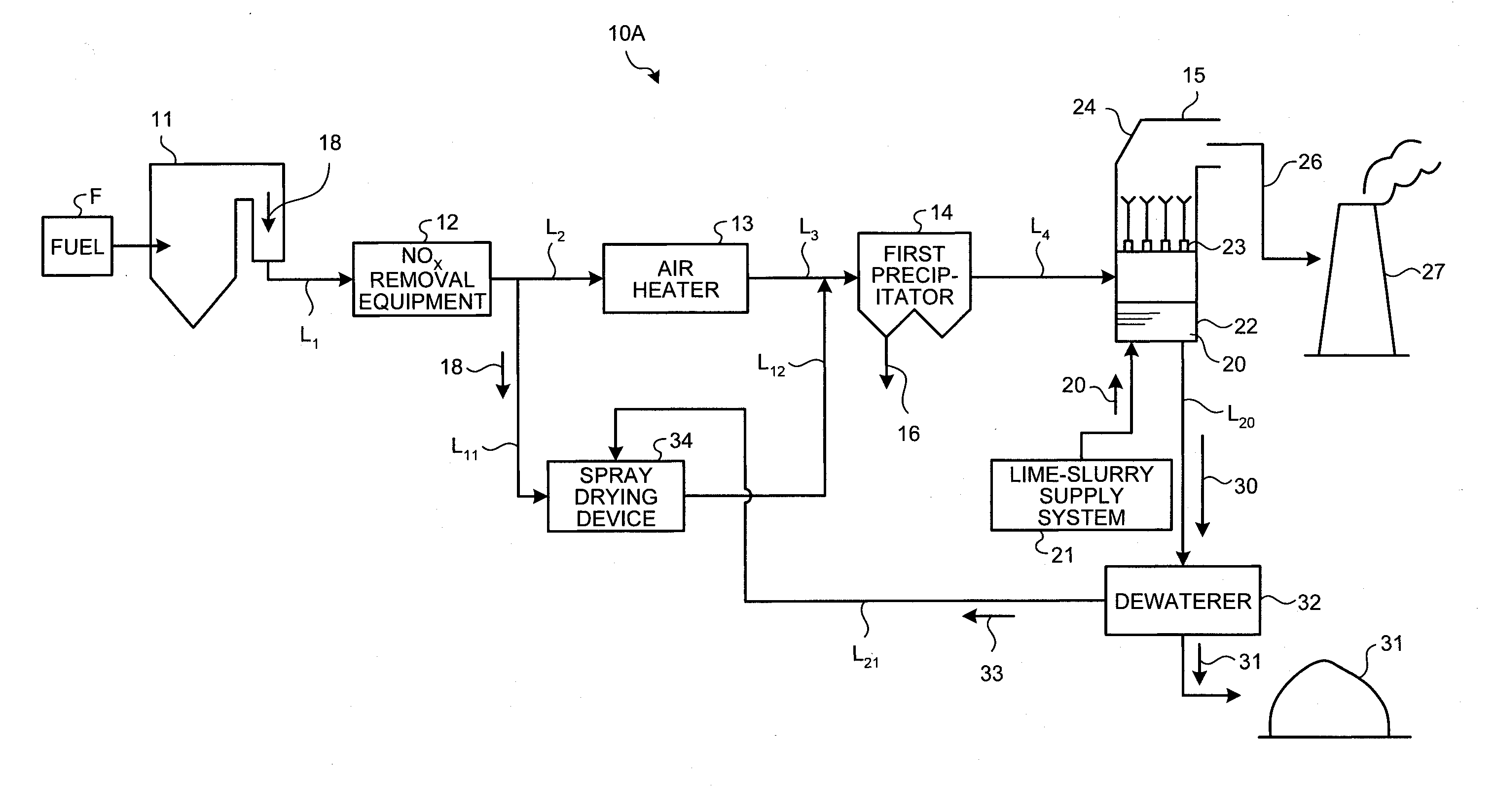
[0068]FIG. 1 is a schematic configuration diagram of an air pollution control system according to a first embodiment of the present invention. An air pollution control system 10A exemplified in FIG. 1 removes harmful substances such as nitrogen oxides (NOx), sulfur oxides (SOX), and mercury (Hg) from flue gas 18 discharged from a boiler 11 such as a coal combustion boiler that uses coals as a fuel or a heavy-oil combustion boiler that uses heavy oil as a fuel.
[0069]The air pollution control system 10A includes the boiler 11 that combusts fuel F, an air heater 13 that recovers heat of the flue gas 18 from the boiler 11, a first precipitator 14 that reduces dust in the flue gas 18 after heat recovery, a desulfurizer 15 that reduces sulfur oxides in the flue gas 18 after dust reduction by a lime slurry 20, which is an absorbent, a dewaterer 32 that reduces gypsum 31 from desulfurization discharged water 30 discharged from the desulfurizer 15, a spray drying device 34 including an atomi...
second embodiment
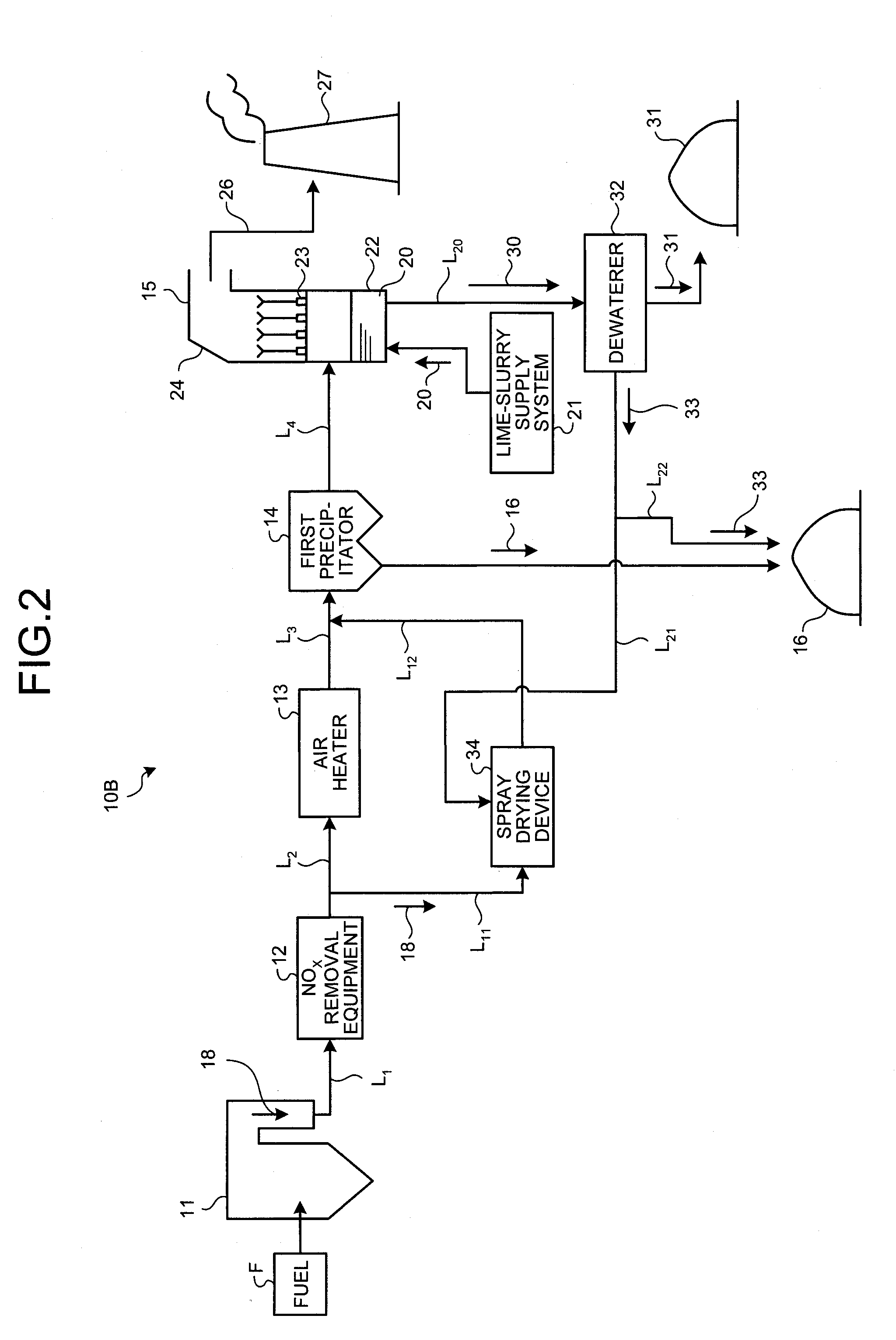
[0091]An air pollution control system according to a second embodiment of the present invention is explained next. Constituent elements identical to those in the first embodiment described above are denoted by like reference signs, and explanations thereof will be omitted. FIG. 3 is a schematic configuration diagram of the air pollution control system according to the second embodiment. In an air pollution control system 10C according to the second embodiment, as shown in FIG. 3, a solid-liquid separating unit 41 that reduces suspended solids (SS) or suspended substance in the dewatering filtration fluid 33 is installed in the dewatering line L21.
[0092]As the solid-liquid separating unit 41, for example, a hydraulic cyclone, a belt filter, a classifier, or a membrane separator can be mentioned.
[0093]The solid-liquid separating unit 41 reduces suspended solids (SS) in the dewatering filtration fluid 33 so that an SS concentration in a separate liquid 42 becomes equal to or less than ...
third embodiment
[0098]An air pollution control system according to a third embodiment of the present invention is explained next. Constituent elements identical to those in the first embodiment described above are denoted by like reference signs, and explanations thereof will be omitted. FIG. 4A is a schematic configuration diagram of the air pollution control system according to the third embodiment. FIG. 4B is a schematic configuration diagram of another air pollution control system according to the third embodiment. FIG. 4C is a schematic configuration diagram of still another air pollution control system according to the third embodiment. In an air pollution control system 10D-1 according to the third embodiment, as shown in FIG. 4A, a small second precipitator 35 is provided on the downstream side of the spray drying device 34 to reduce solid matters.
[0099]As the small second precipitator 35, for example, a bag filter or an electric dust collector can be used. Accordingly, a solid matter 36 ca...
PUM
| Property | Measurement | Unit |
|---|---|---|
| Temperature | aaaaa | aaaaa |
| Circumference | aaaaa | aaaaa |
Abstract
Description
Claims
Application Information