Process for contacting one or more fluids and a reactor relating thereto

a technology of fluid contact and process, which is applied in the direction of water supply installation, physical/chemical process catalysts, transportation and packaging, etc., can solve the problems of difficult mixing of mixed phases of gas and liquid, limited contact between liquid and gas, and deterioration of etc., to achieve the effect of effectively mixing fluids in a vessel, improving the vapor-liquid contact area, and facilitating mixing

Active Publication Date: 2012-09-27
UOP LLC
View PDF2 Cites 19 Cited by
  • Summary
  • Abstract
  • Description
  • Claims
  • Application Information

AI Technical Summary

Benefits of technology

[0008]The embodiments disclosed herein can provide a conduit for effectively mixing fluids in a vessel. Particularly, the conduits can communicate fluids collecting on a tray in a reactor, typically after a first catalyst bed, and route the fluids through a conduit that can be

Problems solved by technology

Generally, mixing is more difficult with mixed phases of gas and liquid due to their differing densities.
Unfortunately, gas and liquid flow from the tray can tend to promptly separate due to the large density differential between the gas a

Method used


Image

  • Process for contacting one or more fluids and a reactor relating thereto
  • Process for contacting one or more fluids and a reactor relating thereto
  • Process for contacting one or more fluids and a reactor relating thereto

Examples


Embodiment Construction

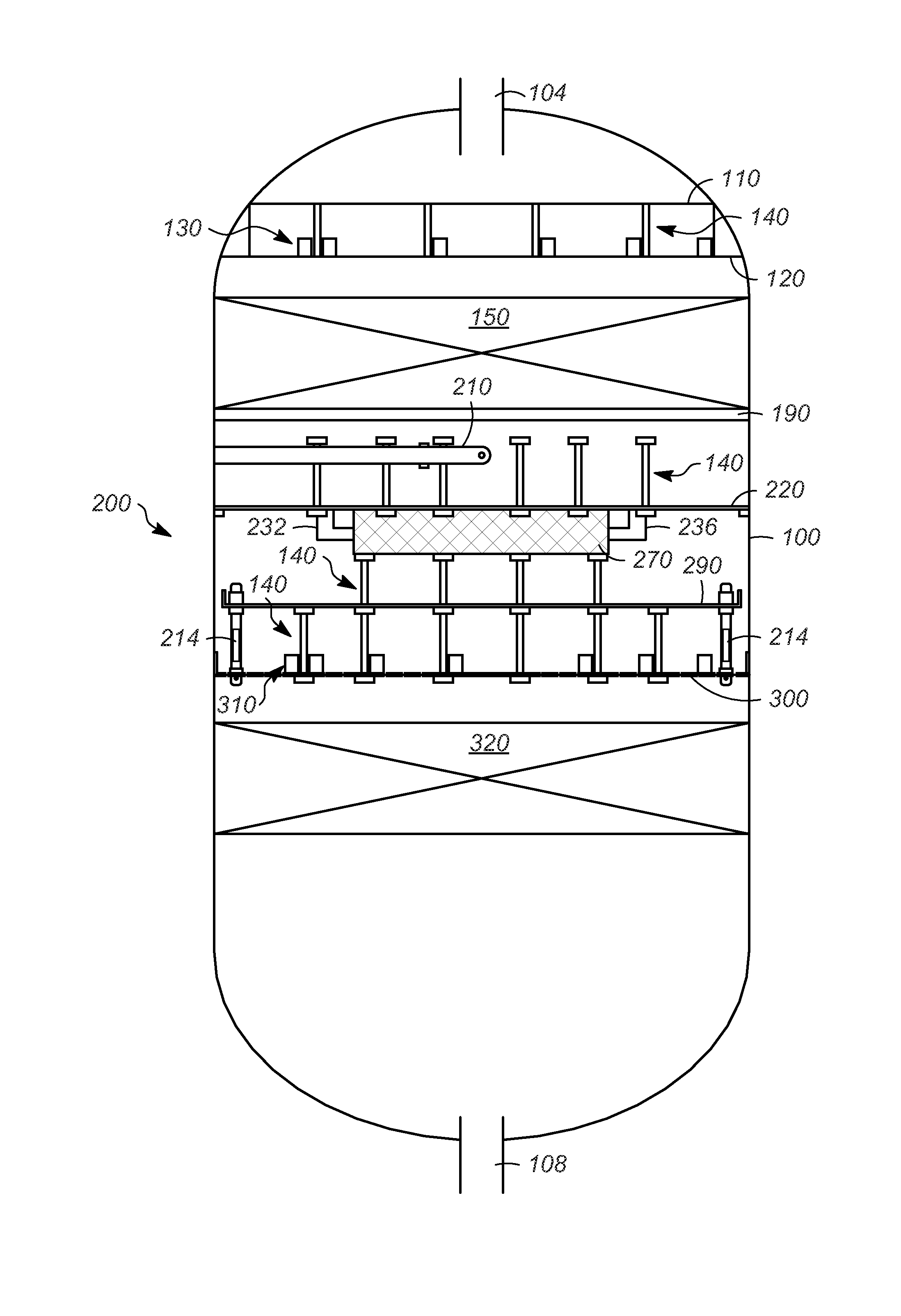
[0023]Referring to FIG. 1, an exemplary vessel or reactor 100 can include an inlet 104 and an outlet 108. Typically, the vessel 100 can be utilized for hydroprocessing reactions and can receive a multitude of fluids. Often, the vessel 100 can receive a liquid as well as one or more, typically a plurality, of vapors. Generally, the vessel or reactor 100 can be any suitable hydroprocessing reactor, such as disclosed in, e.g., U.S. Pat. No. 4,937,051.

[0024]The vessel 100 can contain a first distribution or rough distribution tray 110, a second distribution tray or redistribution tray 120, a plurality of downcomers 130, a series of support beams or trusses 140 at various elevations, a first catalyst bed 150, a quenching and / or mixing zone 200, and a second catalyst bed 320. Generally, the vessel 100 can contain the quenching and / or mixing zone 200 between the first and second catalyst beds 150 and 320. Although two catalyst beds 150 and 320 are depicted, it should be understood that any...


PUM

PropertyMeasurementUnit
Angleaaaaaaaaaa
Timeaaaaaaaaaa

Abstract

One exemplary embodiment can be a process for contacting one or more fluids in a vessel. The process may include passing one or more fluids into a chamber from an overhead tray and providing a conduit outside the chamber coupling a respective spillway to a respective hole for increasing contact time inside the conduit. Typically, the chamber forms one or more sidewalls forming at least one hole and the overhead tray forms at least one spillway.

Description

FIELD OF THE INVENTION[0001]This invention generally relates to a process for contacting one or more fluids, and a reactor relating thereto.DESCRIPTION OF THE RELATED ART[0002]Often, a reactor includes various internal mechanisms therein. Typically, a reactor having a plurality of beds can also include mechanisms, such as mixing devices and distribution trays, to mix and redistribute effluent passing from one catalyst bed to the next.[0003]Typically, an external quench gas is introduced between catalyst beds for cooling an effluent falling from the bed above. The quench gas and the effluent are mixed to evenly distribute temperatures and compositions. Generally, mixing is more difficult with mixed phases of gas and liquid due to their differing densities. The quality of the mixing may depend on the contacting time and area of the two phases. Usually, the gas and liquid flow into a mixing box from a tray and then flow tangentially thereby creating a vortex. The gas and liquid can lea...

Claims


Application Information

Patent Timeline
IPC IPC(8): B01J8/04B01J8/02F15D1/00
CPCB01J8/0453B01D3/008B01J2208/00929B01J8/0492B01J2208/00884Y10T137/0318
Inventor CHEN, PENGFEIXU, ZHANPING
Owner UOP LLC
Why Eureka
Try Eureka