Dust cover structure of hydraulic shock absorber

a technology of hydraulic shock absorbers and dust covers, which is applied in the direction of shock absorbers, vibration dampers, bellows, etc., can solve the problems of high precision, difficult manufacturing, and high precision, and achieve the effect of easy manufacture of dust covers, suppressing bowing, and high precision

Inactive Publication Date: 2012-09-27
SHOWA CORP
View PDF3 Cites 9 Cited by
  • Summary
  • Abstract
  • Description
  • Claims
  • Application Information

AI Technical Summary

Benefits of technology

[0010]An object of the present invention is to easily manufacture a dust cover which can suppress bowing, in a dust cover structure of a hydraulic shock absorber.
[0016]In accordance with the present embodiment, the following operations and effects can be achieved.
[0018]The bellows portions in the upper region and the lower region are easily bent at such a degree that the rigidity is small, but are hard to bend at such a degree that they are shorter in comparison with the whole length of the dust cover, and are immediately folded at such a degree that the rigidity is small, thereby being suppressed from bowing.
[0021](b) It is sufficient to make the thicknesses of the bellows portions in the upper region and the lower region thin as a whole, and make the thickness of the bellows portion in the intermediate region thick as a whole, and a high precision is not required in the molding die and the manufacturing method. It is possible to easily manufacture the dust cover which can suppress the bowing.
[0022](c) The thickness of the bellows portion in the intermediate region is made 5 to 15% thicker than the thicknesses of the bellows portions in the upper region and the lower region. It is possible to securely suppress the bowing of the dust cover by the item (a) mentioned above.
[0023](d) When the hydraulic shock absorber is of the strut type, the damper tube and the piston rod tilt with respect to the vehicle body side attaching bracket. As a result, the dust cover also tilts. At this time, since the dust cover is pushed upward by the extension and retraction of the damper tube in a state of inclining with respect to the vehicle body side attaching bracket, it tends to bow due to this upthrust, and the bowing suppressing effect mentioned in the item (a) is great in the strut type hydraulic shock absorber.

Problems solved by technology

The dust cover described in Patent Document 1 is formed in such a manner that the thickness of the crest portion of the bellows portion is different per each of the regions extending in the longitudinal direction, requires high precision in a molding die and a manufacturing method, and is difficult to manufacture.
The dust cover described in Patent Document 2 is formed in such a manner that the height of the ridge of the bellows portion is different per each of the regions extending in the longitudinal direction, requires high precision in a molding die and a manufacturing method, and is difficult to manufacture.

Method used


Image

  • Dust cover structure of hydraulic shock absorber
  • Dust cover structure of hydraulic shock absorber
  • Dust cover structure of hydraulic shock absorber

Examples


Embodiment Construction

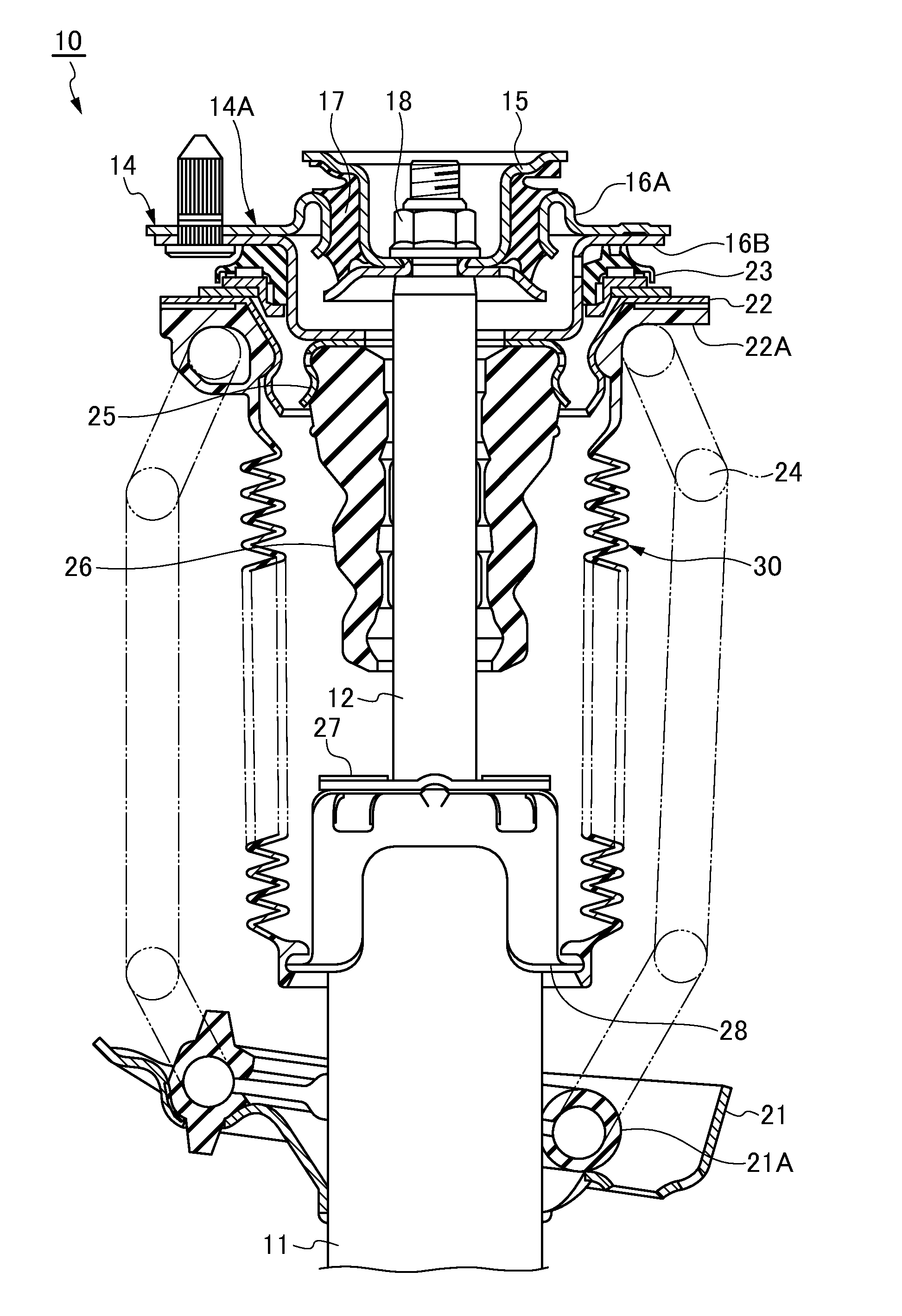
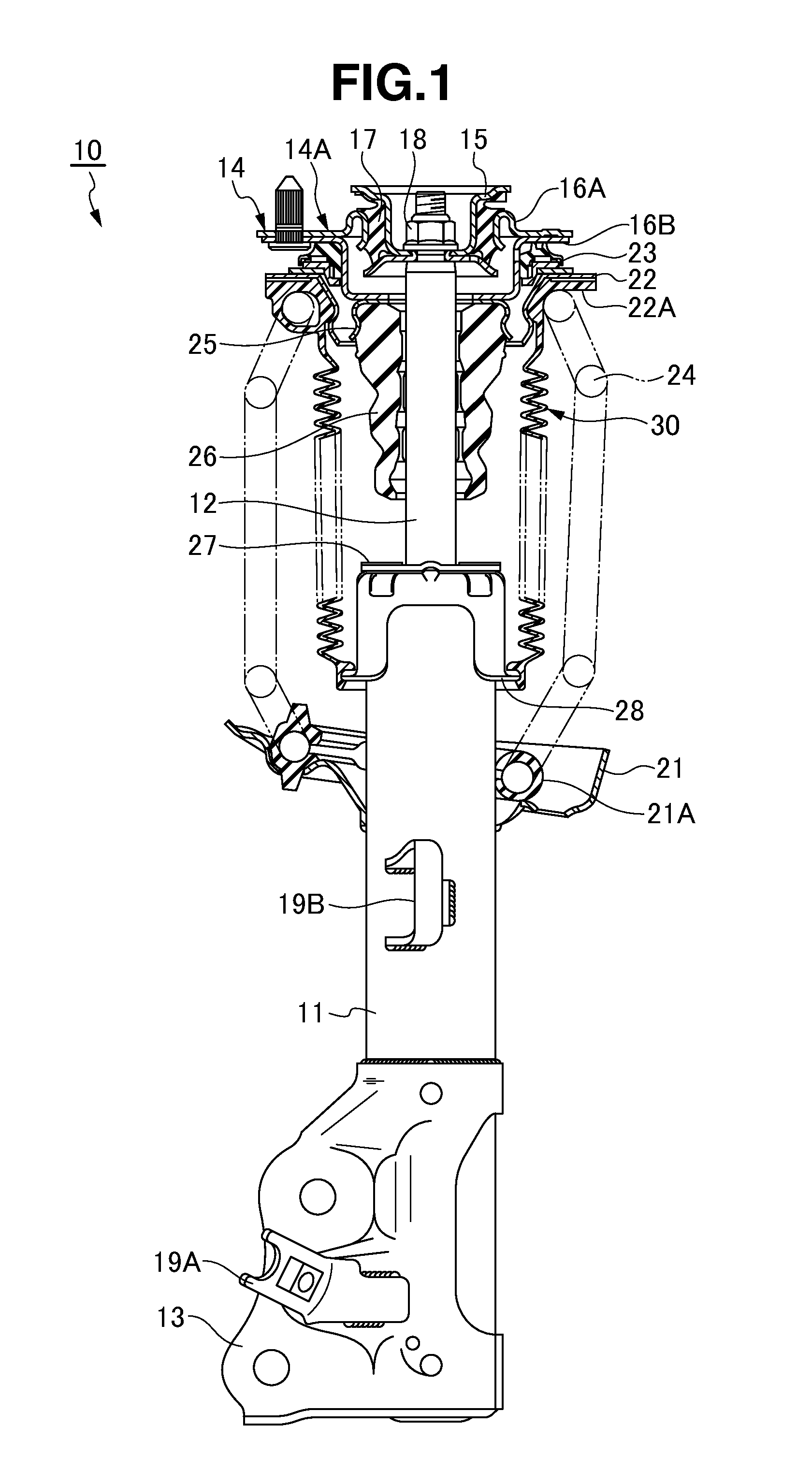
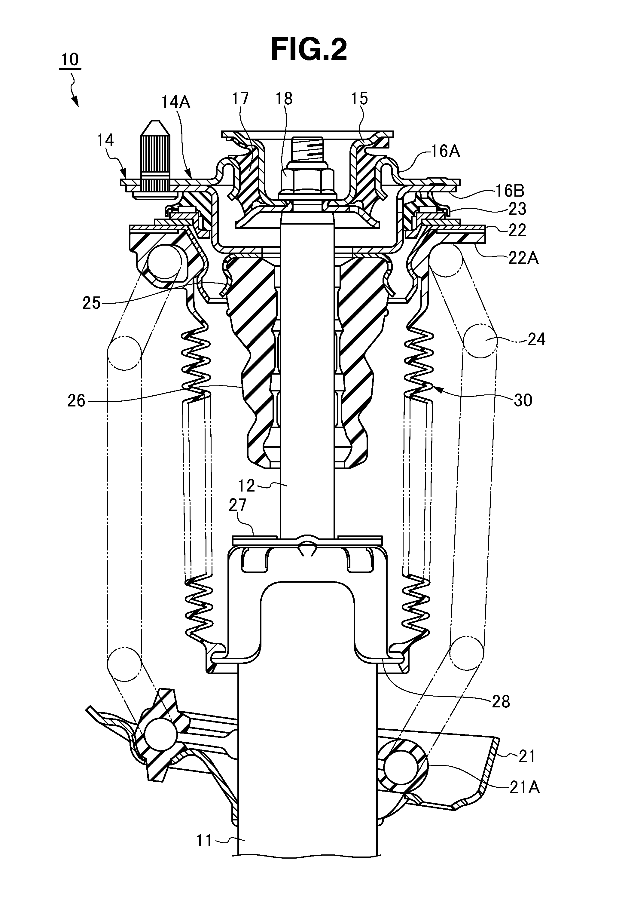
[0029]A hydraulic shock absorber 10 shown in FIGS. 1 and 2 is of a strut type. It is structured such that a piston rod 12 is inserted into a cylinder (not shown) which is embedded in a damper tube 11. A wheel side attaching bracket 13 is provided in the damper tube 11 so as to be connected to a wheel, and is provided with a vehicle body side attaching bracket 14 in the piston rod 12 protruding out of the damper tube 11 so as to be attached to a vehicle body. In this case, the vehicle body side attaching bracket 14 consists of a mount rubber assembly 14A consisting of a stay 15, upper and lower mount bases 16A and 16B, and a mount rubber 17, and is structured by inserting the stay 15 of the mount rubber assembly 14A into an upper end side small diameter portion of the piston rod 12 so as to be fastened by a nut 18.

[0030]The hydraulic shock absorber 10 is provided with a lower arm attaching portion 19A in the wheel side attaching bracket 13, is provided with a lower arm (not shown) be...


PUM


Abstract

In a dust cover structure of a hydraulic shock absorber 10 covering a piston rod 12 of the hydraulic shock absorber 10 with a bellows-like dust cover 30, the dust cover 30 is divided into upper, intermediate and lower regions A, B, and C extending in a longitudinal direction. Thicknesses Ta and Tc of bellows portions 33A and 33C in the upper region A and the lower region C are made thin, and a thickness Tb of a bellows portion 33B in the intermediate region B is made thick.

Description

BACKGROUND OF THE INVENTION[0001]1. Field of the Invention[0002]The present invention relates to a dust cover structure of a hydraulic shock absorber.[0003]2. Description of the Related Art[0004]In a hydraulic shock absorber, a piston rod protruding out of an outer tube is covered by a dust cover, thereby preventing mud from being attached to the piston rod and preventing a stone on a road surface from coming into contact therewith. The dust cover is formed by molding a rubber material or the like in a bellows shape, which extends and retracts in accordance with extension and retraction of the piston rod.[0005]In the dust cover, a bellows portion deflects largely to one side in a radial direction in the middle of the compression (hereinafter, referred to as a bowing), and there is a risk that it comes into contact with a coil spring or the like in the periphery so as to be broken.[0006]Accordingly, in a dust cover described in Japanese Patent Application Laid-Open No. 10-159975 (Pat...

Claims


Application Information

Patent Timeline
Patent Type & Authority Applications(United States)
IPC IPC(8): F16F9/38
CPCF16J3/041F16F9/38
Inventor MURAGUCHI, NOBUYUKI
Owner SHOWA CORP
Why Eureka
Try Eureka