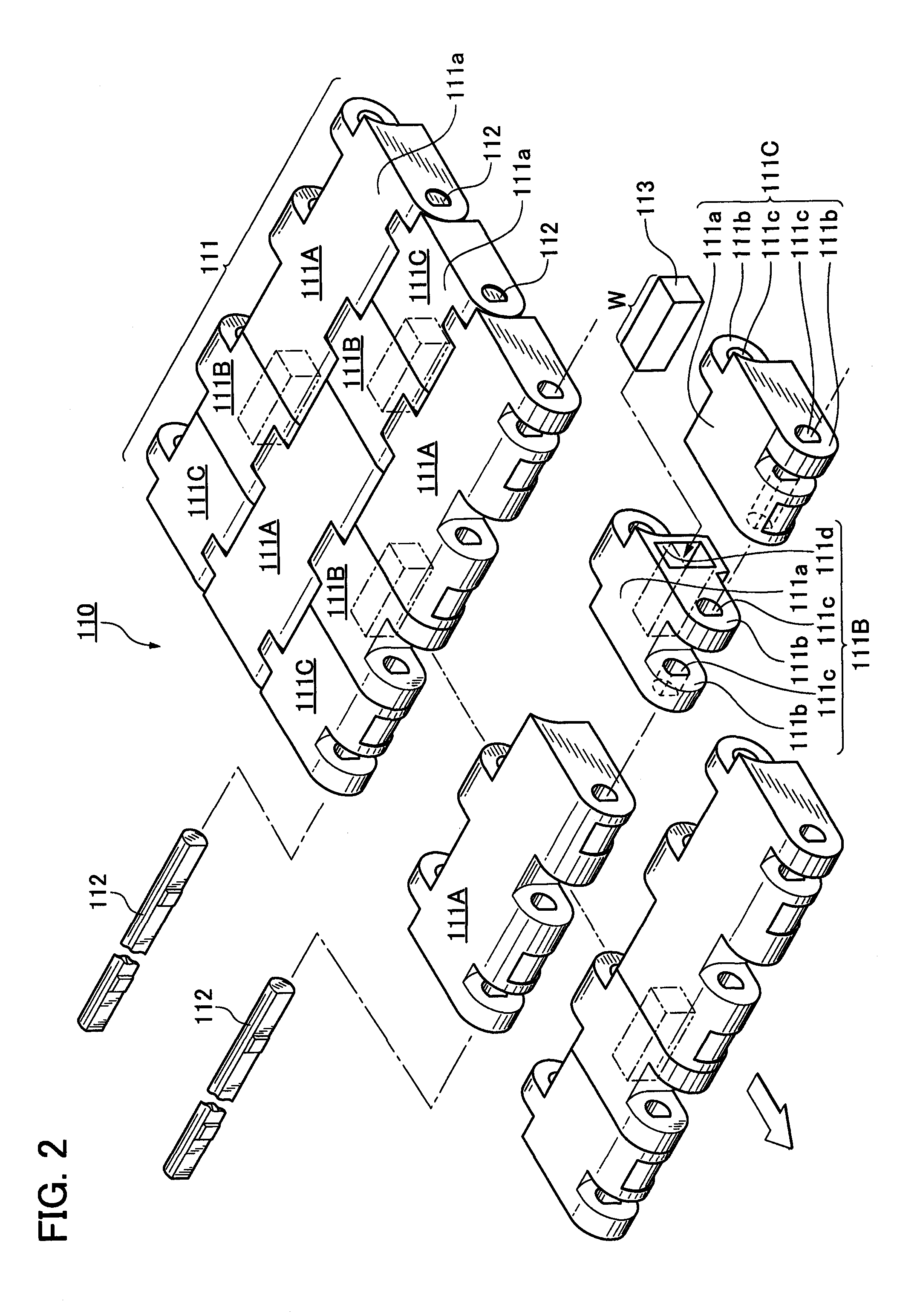
[0020]According to the first aspect of the chain conveyor system of the invention, because the chain conveyor system comprises the conveyor chain having the plurality of
synthetic resin links with laterally adjoining modules having the loading surfaces, and link pins for linking the
synthetic resin links with each other in the chain longitudinal direction, and because the sprockets that are wrapped by and engage with the conveyor chain, the
synthetic resin link modules of the conveyor chain synergistically exhibit attractive force and
impact absorbing force and absorb impacts and vibrations of the metallic magnetic articles that are otherwise prone to occur during conveyance of the articles. Therefore, it is possible not only to convey the articles by securely attracting and retaining the articles even on a conveying line inclined upward or downward or on a slippery wet conveyor line but also to avoid damages and vibration
noise caused by impacts of the metallic magnetic articles.
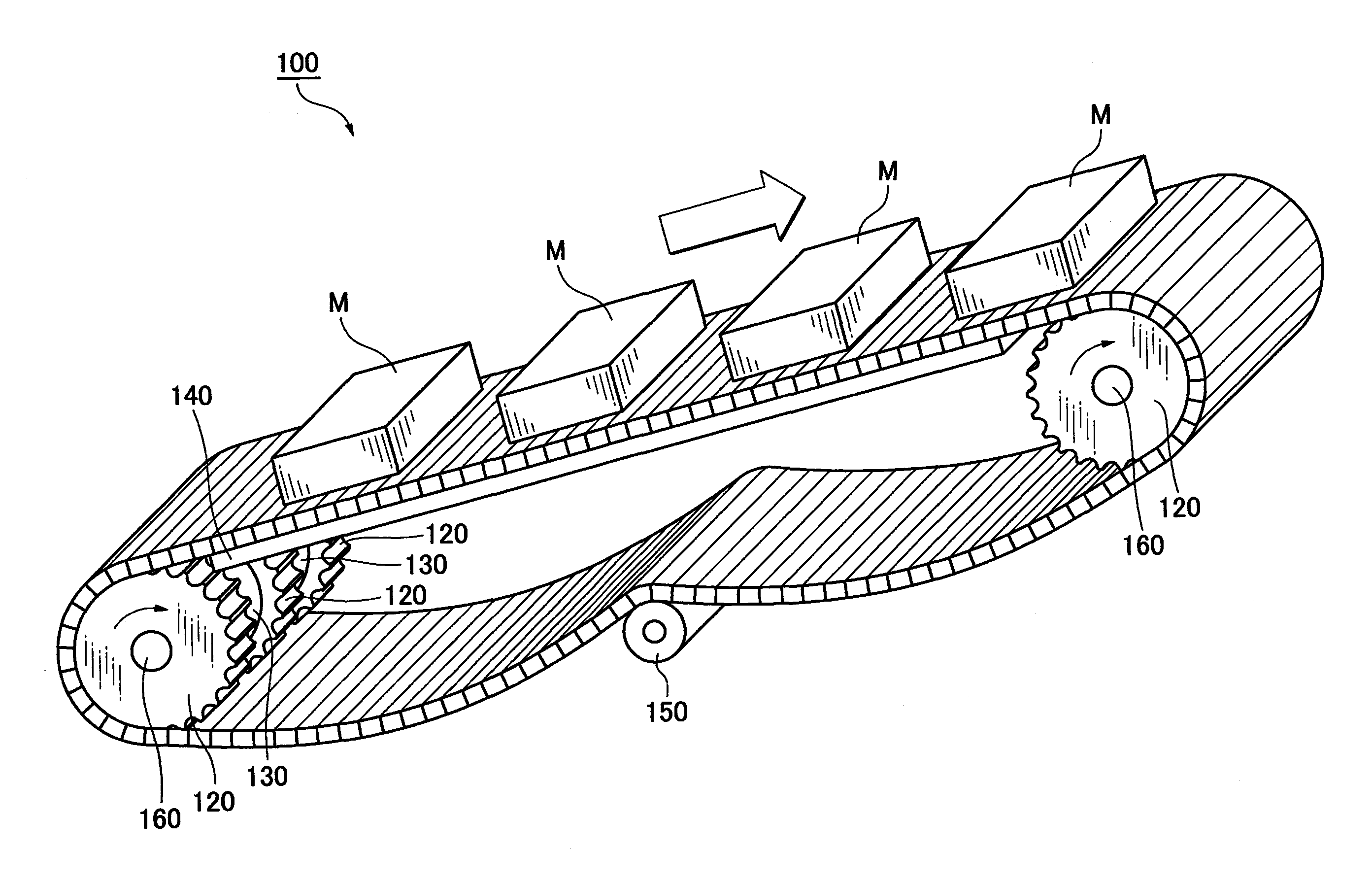
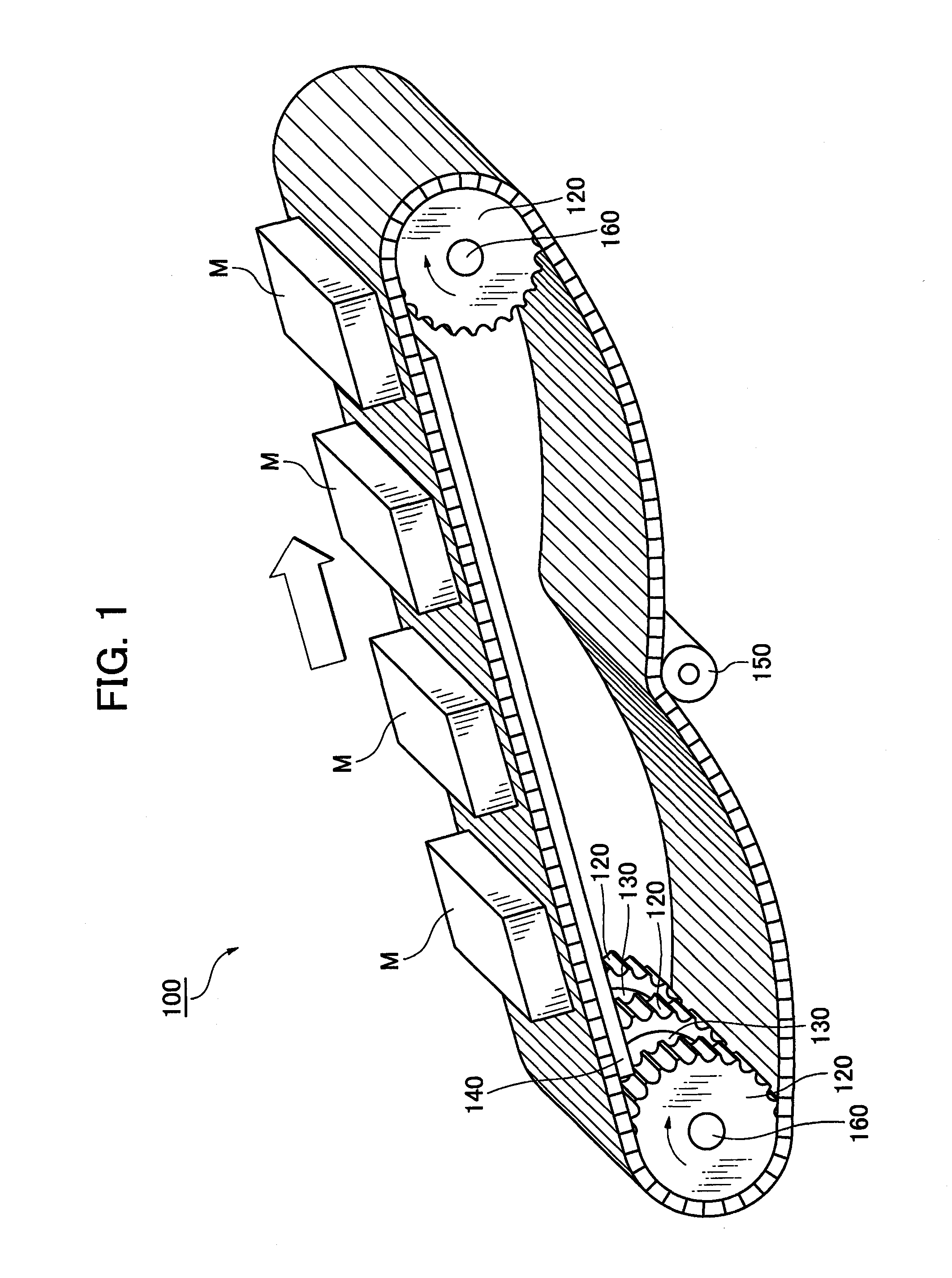
[0021]Because the conveyor chain further comprises the magnet-piece-storing chambers formed within the synthetic resin link modules and the article-attracting magnet pieces that are stored in the magnet-piece-storing chambers and move from the inner circumferential side to the outer circumferential side of the chain within the magnet-piece-storing chambers to attract and retain the articles on the loading surfaces, and because the article-separating means disposed coaxially with the sprockets comprises, on the outer circumferential parts thereof, the article-separating magnet pieces for separating the articles attracted by the synthetic resin link modules by attracting the article-attracting magnet pieces within the magnet-piece-storing chambers formed in the synthetic resin link modules that are wrapped around the article-separating means, so they are displaced from the outer circumferential side where the article-attracting magnet pieces attract the metallic magnetic articles, to the inner circumferential side position of the chain where the article-separating magnet pieces attract the article-separating magnet pieces within in the magnet-piece-storing chambers. As a result, prior to engagement with the
sprocket, the link modules effectively attract the articles, and after engaging the
sprocket, the modules allow the articles to separate from the chain. Therefore, the chain conveyor system can smoothly transfer the metallic magnetic articles to a succeeding conveyor line or other equipment in a conveyor terminal carry-out area in which the sprockets having the coaxial article-separating means are disposed without unintentionally continuing to attract the articles, i.e., the system can realize a so-called steady
relay or transfer.
[0022]According to the second aspect of the chain conveyor system of the invention, because the article-separating magnet pieces of the article-separating means are disposed respectively so as to register with the article-attracting magnet pieces of the synthetic resin link modules and attract each other, it becomes possible to achieve smooth transfer by exhibiting both attractive forces in maximum and steadily when separating the articles without requiring phase shift in the separation timing of the article-separating means.
[0023]According to the third aspect of the chain conveyor system of the invention, because the attractive force of the article-separating magnet piece to the article-attracting magnet piece is greater than the attractive force of the article-attracting magnet piece, the attraction between the article-separating magnet piece of the article-separating means and the article-attracting magnet piece of the synthetic resin link module strongly surpasses the attraction between the article-attracting magnet piece and the article. Therefore, it become possible to improve reliability of the
relay or transfer by powerfully attracting the article-attracting magnet piece of the synthetic resin link module from the outer circumferential side to the inner circumferential side of the chain within the magnet-piece-storing chamber to interrupt the attraction with the article instantly.
[0024]According to the fourth aspect of the chain conveyor system of the invention, because the article-separating means is composed of a free roller coaxially supported through a bearing on the same shaft that supports sprocket that is wrapped by and engages with the conveyor chain, and because the article-separating magnet pieces of the article-separating means and the article-attracting magnet pieces of the synthetic resin link modules attract each other following the engagement of the chain with the sprocket, and pass out of registry upon disengagement of the chain from the sprocket, it becomes possible to reliably attract the articles prior to engagement of the chain with a sprocket and thereafter separate the articles with the movement of the chain around the sprocket.
[0025]According to the fifth aspect of the chain conveyor system of the invention, because the article-attracting magnet pieces extend on both sides in the conveyor width direction within the conveyor chain, the article-attracting magnet pieces within the synthetic resin link modules move all together on both sides in the conveyor width direction between the outer circumferential side and the inner circumferential side of the chain within the permanent magnet storing chambers and forcibly attract or separate the articles corresponding to the engagement and disengagement states of the conveyor chain relative to the sprocket. Therefore, the chain conveyor system can smoothly
discharge the metallic magnetic articles to a succeeding conveyor line or to other equipment in a conveyor terminal carry-out area in which the sprocket coaxially having the article-separating means is disposed without unintentionally biasing loading orientation of the articles, i.e., can realize a so-called steady relay or transfer while keeping a loading attitude.

