
Welding Method and Welding Apparatus

Active Publication Date: 2012-09-27
KOITO MFG CO LTD
View PDF11 Cites 9 Cited by
  • Summary
  • Abstract
  • Description
  • Claims
  • Application Information

AI Technical Summary

Benefits of technology

[0010]It is, therefore, an object of the present invention to provide a welding method and a welding apparatus that are capable of reducing the reflection loss of radiated light that is controlled for deflection, thus realizing welding with high welding efficiency.
[0012]The above-described object is also accomplished by a unique structure of the present invention for a welding apparatus that includes a means for holding a first member and a light transmissive second member in a close contact state, and a light deflecting means for controlling light emitted from a light source for deflection and radiating the deflected light to the closely contacting surfaces from a second member side, and in the present invention, the welding apparatus further includes a reflectance reducing means which is for reducing the reflectance of the radiated light and disposed on the light receiving surface side of the second member.
[0013]In the above-described welding method and apparatus of the present invention, the reflectance reducing means is configured by an optical step that reduces an incident angle of the light entering the closely contacting surfaces of the first and second members, and alternatively, the reflectance reducing means can be configured by laminating a plurality of light transmissive members having different refractive indices. The reflectance reducing means of the present invention is preferably formed in a pressing means that is for closely contacting the second member to the first member.
[0014]According to the present invention, the light radiated to a weld interface formed by first and second members is reduced, by a reflectance reducing means, in its reflectance that is until the light is radiated to the second member, so that a reflection loss of the light being radiated to the second member can be reduced and highly efficient welding can be performed.

Problems solved by technology

Such reflectance loss causes a significant reduction in welding efficiency at the weld interface by laser light and creates the problems of increased welding time and difficulty in obtaining a high-quality weld.
In particular, for a lamp housing that includes a wraparound portion so as to comply with a vehicular lamp that has a wraparound shape as described above, the incident angle of the laser light at the wraparound portion often exceeds the predetermined angle and results in significant reflection loss.

Method used


Image

  • Welding Method and Welding Apparatus
  • Welding Method and Welding Apparatus
  • Welding Method and Welding Apparatus

Examples


first embodiment

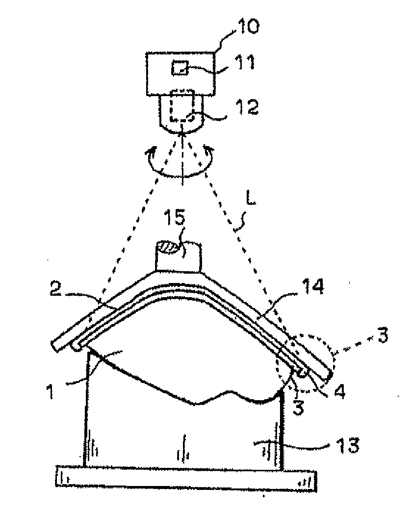
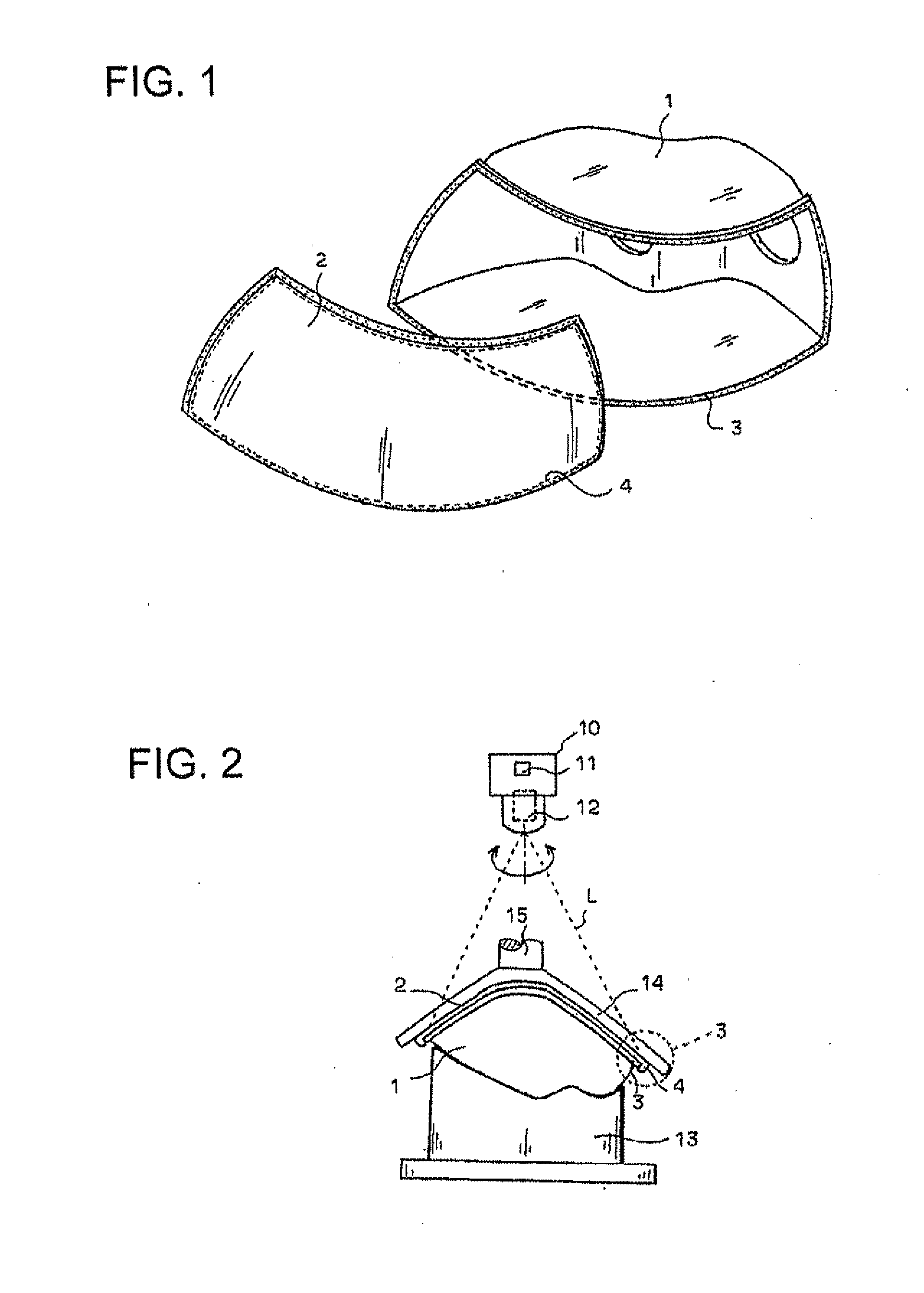
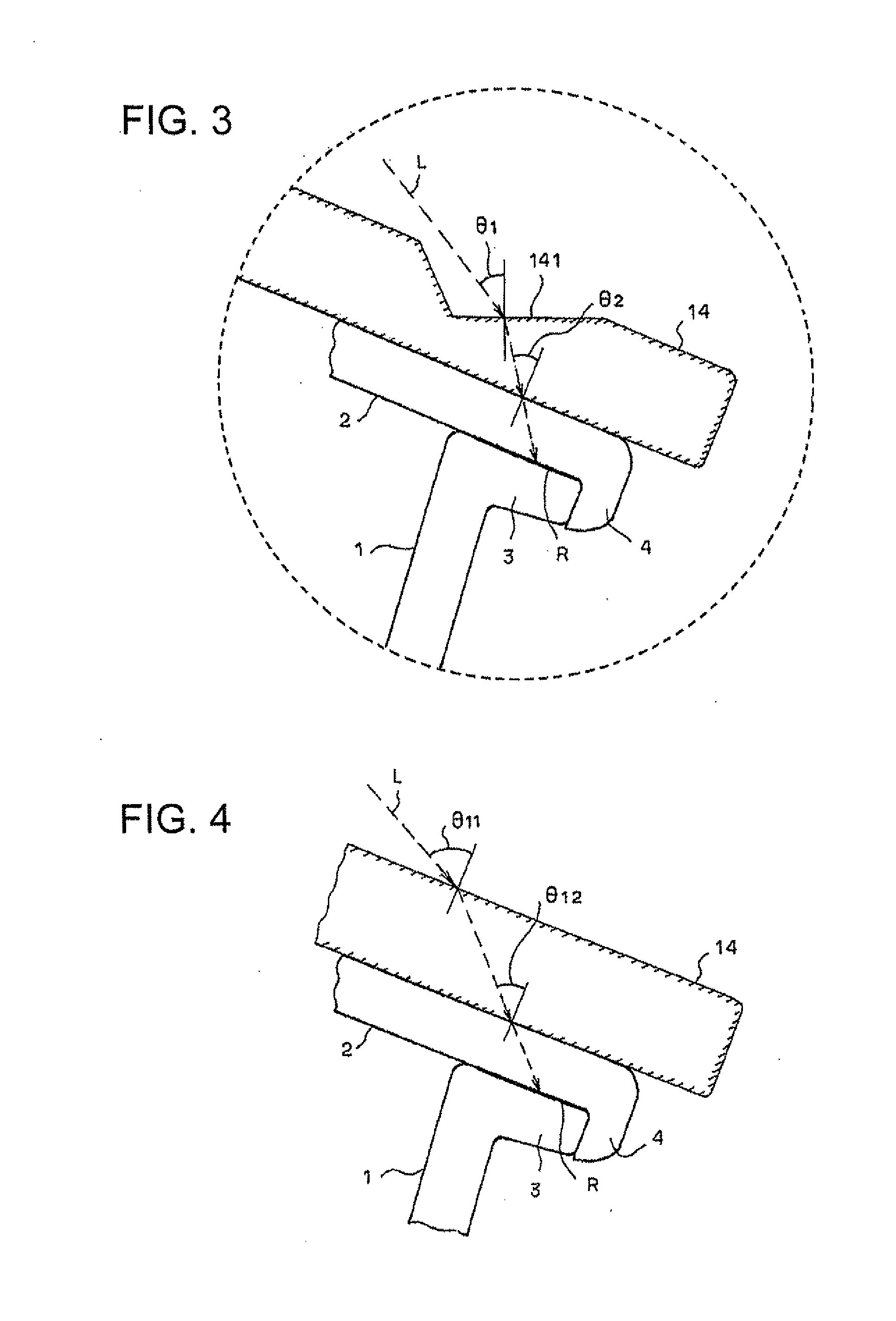
[0026]In the welding apparatus of the structure described above, according to the first embodiment of the present invention, a portion of the cover plate 14 provided in the front cover 2 configures a reflectance reducing means. The reflectance reducing means has a function that reduces an incident angle of laser light L, emitted from the light deflecting device 10 when the laser light L is radiated to the outer surface of the front cover 2, to less than the predetermined angle previously described, in this case, to less than 40 degrees. The cover plate 14 has a similar function as heretofore described for pressing the front cover 2 against the lamp body 1.

[0027]A stem 15 is provided on a portion of the cover plate 14 and is connected to a pressing mechanism not shown in the figure, whereby the cover plate 14 presses the front cover 2 toward the lamp body 1 when the pressing mechanism is operated, and adhesion is secured at a weld interface of the flange 3 of the lamp body 1 and the ...

second embodiment

[0045]FIG. 8 is a cross-sectional view that shows a second embodiment of the present invention in which a cover plate 14B serves as a reflectance reducing means of the present invention.

[0046]In this second embodiment, the cover plate 14B is not provided with an incident angle adjusting step. Instead, a plurality of light transmissive thin films with different refractive indices are laminated by coating or the like onto a cover plate 14a that has a single-plate structure. More specifically, first, second, and third light transmissive films 14b, 14c, and 14d having successively smaller refractive indices nb, nc, nd (nb>nc>nd) in this order are laminated in a state of close contact. In this example, the refractive index nb of the first light transmissive film 14b is equal to the refractive indices of the cover plate 14a and front cover 2.

[0047]In this second embodiment, the incident angle θ11 of the laser light L entering the cover plate 14B is the same as that in the first embodiment...


PUM

PropertyMeasurementUnit
Angleaaaaaaaaaa
Refractive indexaaaaaaaaaa
Reflectanceaaaaaaaaaa

Abstract

A welding technique closely contacting a light transmissive second member to a first member and radiating deflection-controlled laser light from a second member side to weld both first and second members at a weld interface thereof. A reflectance reducing means is formed by an incident angle adjusting step provided in a cover plate that is disposed on a light radiating surface side of the second member. The reflectance reducing means reduces incident angles of the light at the light radiating surfaces of the first and second members, thus reducing the reflection loss of the laser light at the light radiating surfaces and improving the welding efficiency.

Description

BACKGROUND OF THE INVENTION[0001]1. Field of the Invention[0002]The present invention relates to a welding method and a welding apparatus that are capable of increasing welding efficiency when light such as laser light is radiated to weld an object to be processed.[0003]2. Description of the Related Art[0004]As part of the process to manufacture a vehicular lamp, there is a process that fixedly attaches in an integrated manner a transparent front cover to a container-like lamp body, and welding is used in this process to fixedly attach the front cover to the lamp body. When a lamp housing is configured, for example as shown in FIG. 1, from a container-like lamp body 1 whose front surface has an opening, and a transparent front cover 2 that is made of resin and is fixedly attached to cover the front opening of the lamp body 1, a flange 3 is formed along the peripheral edge of the front opening of the lamp body 1, and this front surface of the flange 3 is brought into closely contact ...

Claims


Application Information

Patent Timeline
IPC IPC(8): B23K26/00B29C65/16
CPCB29L2031/747B29C65/1693B29C65/1635B29C65/1661B29C65/1677B29C65/1687B29C66/1222B29C66/1224B29C66/131B29C66/301B29C66/542B29C66/8122B29C66/81267B29C66/81266B29K2995/0031B29C65/7841B29K2869/00B29K2909/08B29C66/8322B29C66/73921B29K2995/0027
Inventor SAGESAKA, YUJISATO, MASAKAZU
Owner KOITO MFG CO LTD
Features
  • Generate Ideas
  • Intellectual Property
  • Life Sciences
  • Materials
  • Tech Scout
  • Unparalleled Data Quality
  • Higher Quality Content
  • 60% Fewer Hallucinations
Learn More