
Omnidirectional Camera

a technology of omnidirectional camera and omnidirectional lens, which is applied in the field of omnidirectional camera, can solve the problems of important heat effective release and the inability of omnidirectional camera to normally operate, and achieve the effect of effective heat releas

Active Publication Date: 2012-09-27
KK TOPCON
View PDF24 Cites 25 Cited by
  • Summary
  • Abstract
  • Description
  • Claims
  • Application Information

AI Technical Summary

Benefits of technology

[0005]It is an object of the present invention to provide an omnidirectional camera which can be used in high temperature and under the direct sunlight.
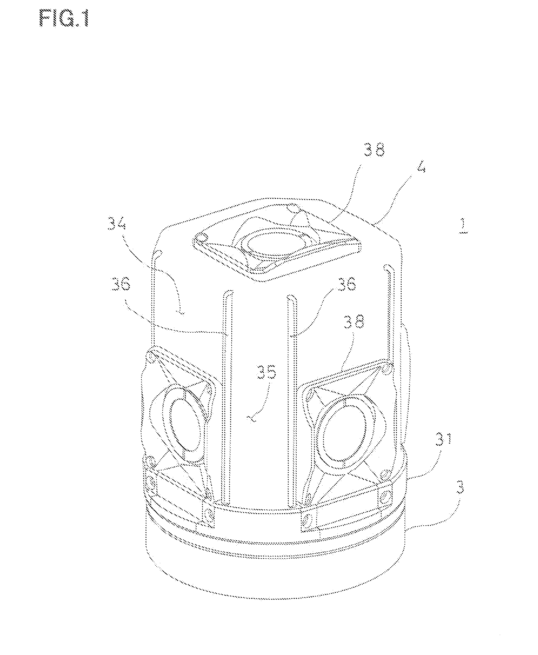
[0011]According to the present invention, the omnidirectional camera comprises two or more camera units, a camera assembly in which the two or more camera units are mounted, a heat shield cover to accommodate the camera assembly, a heat insulating member interposed between the camera assembly and the heat shield cover, a space formed between the camera assembly and the heat shield cover, a required number of slit formed in the heat shield cover and extending in up-and-down direction, and in the omnidirectional camera, the space communicates with an outside through the slit. As a result, the camera assembly and the heat shield cover are thermally insulated from each other, and even if the omnidirectional camera is used in high temperature and under the direct sunlight and a temperature of the heat shield cover is high, the direct sunlight is blocked by the heat shield cover and a temperature of the camera assembly is prevented from being high. Further, even if the space inside of the heat shield cover is heated, the temperature inside the heat shield cover is prevented from being high by a heat releasing of the slit.
[0013]Further, according to the present invention, in the omnidirectional camera, radiation fins are formed on a surface of the camera assembly. As a result, a heat is effectively released from the surface of the camera assembly.
[0014]Further, according to the present invention, in the omnidirectional camera, the camera assembly has a liquid-tight structure. As a result, even if it is designed so that the slit is formed on the heat shield cover and the heat shield cover communicate with inside and outside, outdoor use is possible in bad weather, such as rainy weather or the like.
[0015]Further, according to the present invention, in the omnidirectional camera, a gap is formed between the heat insulating member and the heat shield cover, the space partitioned by the heat insulating member is communicated through the gap. As a result, a heat is effectively released without blocking a convection of air inside of the camera assembly.

Problems solved by technology

In particular, since the omnidirectional camera integrally accommodates a plurality of cameras therein, effectively releasing the heat is an important problem.
In particular, the use at a high temperature and further under the direct sunlight is a harsh environment for the omnidirectional camera, and the omnidirectional camera may not normally operate due to a high temperature in some cases.

Method used


Image

  • Omnidirectional Camera
  • Omnidirectional Camera
  • Omnidirectional Camera

Examples


Embodiment Construction

[0022]Description will be given on embodiments of the present invention by referring to the attached drawings.

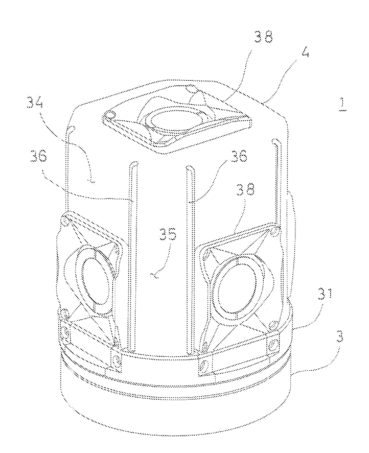
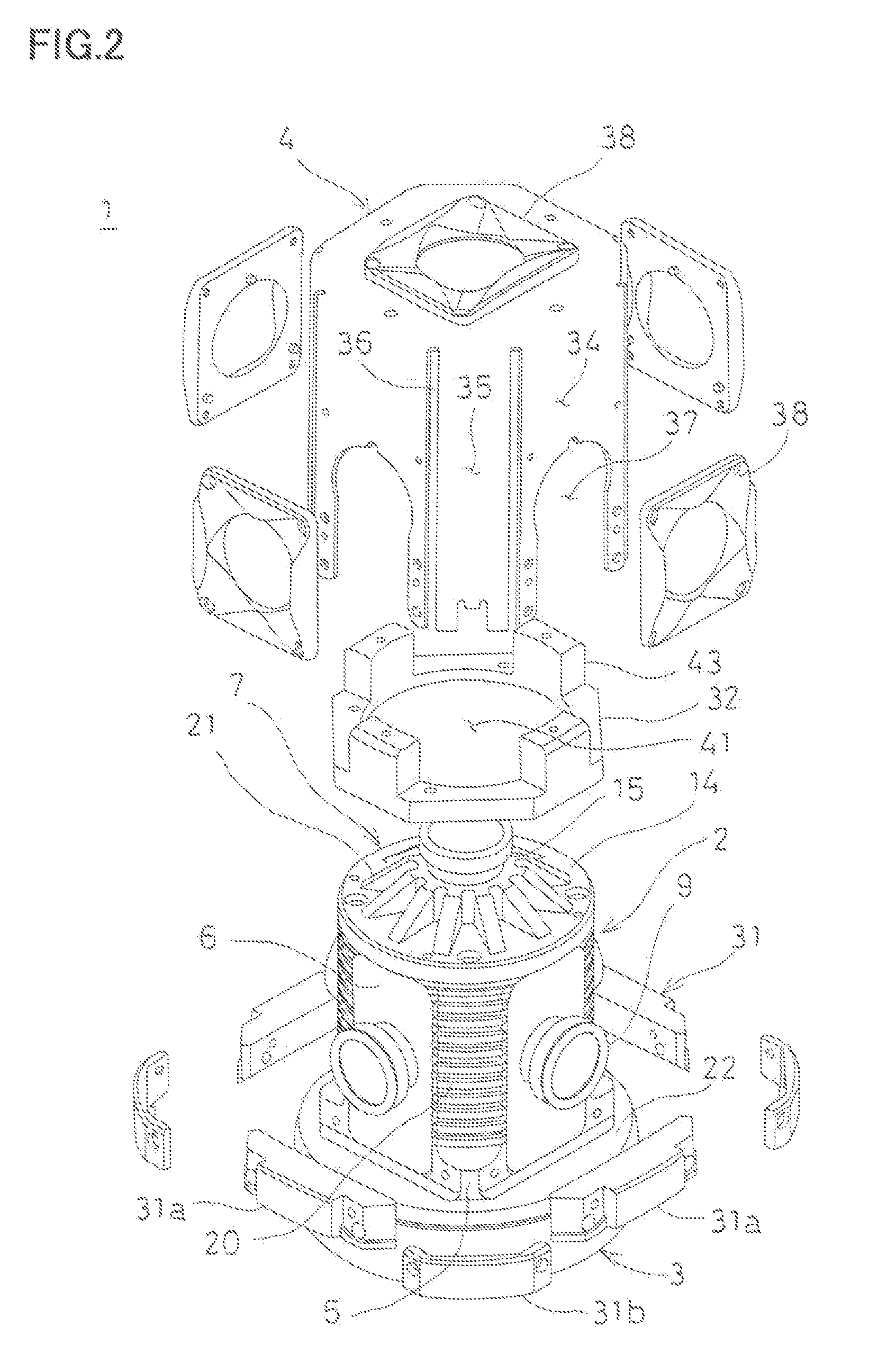
[0023]FIG. 1 and FIG. 2 show appearance of an omnidirectional camera 1 according to an embodiment of the present invention.

[0024]The omnidirectional camera 1 mainly includes a camera assembly 2, an image processing unit 3 accommodating an image processing integrated circuit, an electronic circuit, and others, and a heat shield cover 4 with good ventilation.

[0025]The camera assembly 2 has a camera mounting frame 5 made of a metal material with good heat transfer properties such as aluminum or copper or the like, the camera mounting frame 5 is a cylindrical hollow body having a circular cross section, and four horizontal camera units 6 and a vertical camera unit 7 are provided in the camera mounting frame 5. A total of four horizontal camera units 6 are present on a horizontal plane orthogonal to a center line of the camera mounting frame 5, and each two-unit is arranged respe...


PUM


Abstract

An omnidirectional camera comprises two or more camera units 6, 7, a camera assembly 2 in which the two or more camera units are mounted, a heat shield cover 4 to accommodate the camera assembly, a heat insulating member interposed between the camera assembly and the heat shield cover, a space formed between the camera assembly and the heat shield cover, a required number of slit 36 formed in the heat shield cover and extending in up-and-down direction, and in the omnidirectional camera, the space communicates with an outside through the slit.

Description

BACKGROUND OF THE INVENTION[0001]The present invention relates to an omnidirectional camera which is provided with a plurality of cameras and which takes an image of an omnidirectional view.[0002]In recent years, with spread of a navigation system, not only a positional information as an information of an electronic map but also an image information of a target, buildings, a landscape around a road, and others is required. Therefore, the measurement for acquiring the positional data as the map information is carried out and, at the same time, the image data is acquired by an omnidirectional camera.[0003]In recent years, increase of pixel and increase in a photographing speed of an image pickup element are attempted with increase in a resolution of an omnidirectional camera. On the other hand, the realization of high pixel involves the generation of high heat of the image pickup element, and the increase in the photographing speed involves the generation of high heat of an electronic...

Claims


Application Information

Patent Timeline
Patent Type & Authority Applications(United States)
IPC IPC(8): H04N7/18H04N23/90H04N25/00
CPCH04N5/247H04N7/181G03B11/04H04N5/23238G03B17/55G03B37/04H04N23/45H04N23/55H04N23/698H04N23/90G03B17/00
Inventor SASAGAWA, JUNYAMADA, HIROKAZU
Owner KK TOPCON
Learn More