Apparatus and Method for Dynamically Controlling Light Transmission

a dynamic control and light transmission technology, applied in the field of electric controllable optical devices, can solve problems such as non-uniform spatial distribution, and achieve the effect of low optical power

Inactive Publication Date: 2012-09-27
POINT FINANCIAL
View PDF5 Cites 25 Cited by
  • Summary
  • Abstract
  • Description
  • Claims
  • Application Information

AI Technical Summary

Benefits of technology

[0003]In accordance with a first embodiment of the present invention, an apparatus is provided for controlling the cross-sectional area of a transmitting region through which light may pass from an optical input to an optical output. A liquid crystal orienting matrix layer is located between the optical input and the optical output, and a plurality of dichroic particles is dispersed within it. The dichroic particles are influenced by proximate molecules of the liquid crystal matrix such that reorientation of the proximate liquid crystal molecules results in reorientation of the dichroic particles. In a first orientation, the dichroic particles cause no significant obstruction of light between the optical input and the optical output, while in a second orientation they create a significant obstruction of the light. An electric field generation system (or “generator”) is used to provide an electric field across the liquid crystal layer that has a dynamically variable spatial profile. This creates a spatially non uniform field strength that causes a reorientation of liquid crystal molecules mainly within a predetermined cross section of the liquid crystal layer. Thus, by changing the spatial profile of the electric field, the size and / or shape of the cross-sectional area through which light may pass is changed.
[0005]In another embodiment of the invention, the liquid crystal orienting matrix and the plurality of dichroic particles form a first cell that may be controlled to provide variable obstruction of a first light portion having a first polarization. In addition to this first cell there is a second cell that also includes a liquid crystal orienting matrix and a plurality of dichroic particles, the second cell being controllable to provide variable obstruction of a second light portion having a second polarization perpendicular to the first polarization. The use of these two cells together allows the invention to control both perpendicular polarizations of an unpolarized light source at the optical input. The dichroic particles of the invention may also have a limited wavelength range over which they obstruct light and outside of which the dichroic particles have a relatively higher degree of light transmission. Different types of dichroic particles with different limited wavelength ranges may also be used in the same apparatus. For example, if multiple such different types of dichroic particles are dispersed in multiple different liquid crystal orienting matrixes that are independently controllable, the obstruction of light may be wavelength dependent, allowing the apparatus to have a predetermined spectral response.
[0010]In another variation of this embodiment, two layers of liquid crystal lenses are arranged parallel with each other such that their lenses are aligned in a direction along which light passes from the optical input to the optical output. Between these two layers is positioned an aperture layer that is opaque except for a plurality of apertures each aligned with an optical axis passing through adjacent lenses of the first and second liquid crystal layers. The apertures each have a cross-sectional area significantly smaller than that of the lenses such that, when the lenses are in a state relatively low optical power, a majority of light passing through a lens of the first layer is blocked by the aperture layer before reaching the corresponding lens of the second layer. However, when the lenses are in a state of relatively high power, the majority of light reaching each lens of the first layer is focused through its corresponding aperture and is incident on the corresponding lens of the second layer. Each corresponding lens of the second layer then recollimates the light so that an image of the optical input is readily available at the optical output.

Problems solved by technology

This creates a spatially non uniform field strength that causes a reorientation of liquid crystal molecules mainly within a predetermined cross section of the liquid crystal layer.

Method used


Image

  • Apparatus and Method for Dynamically Controlling Light Transmission
  • Apparatus and Method for Dynamically Controlling Light Transmission
  • Apparatus and Method for Dynamically Controlling Light Transmission

Examples


Embodiment Construction

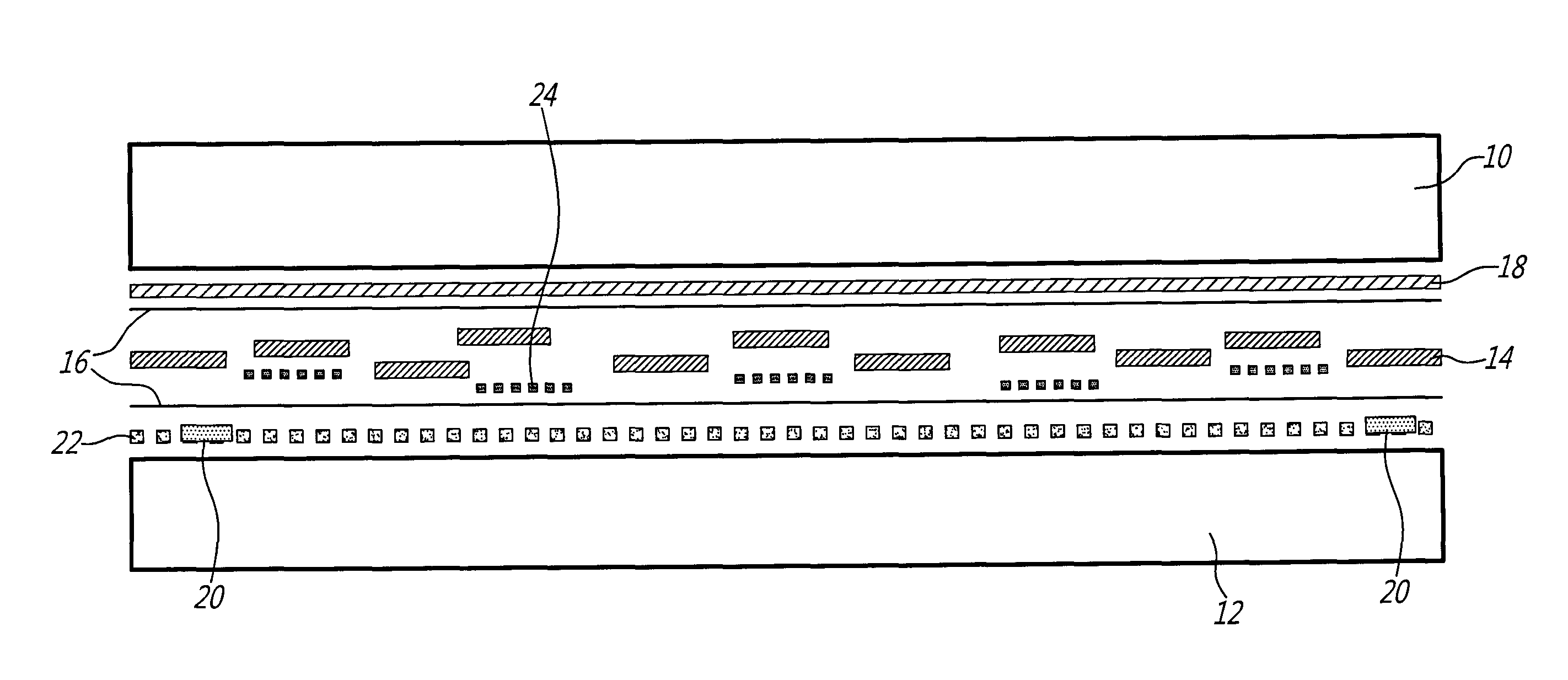
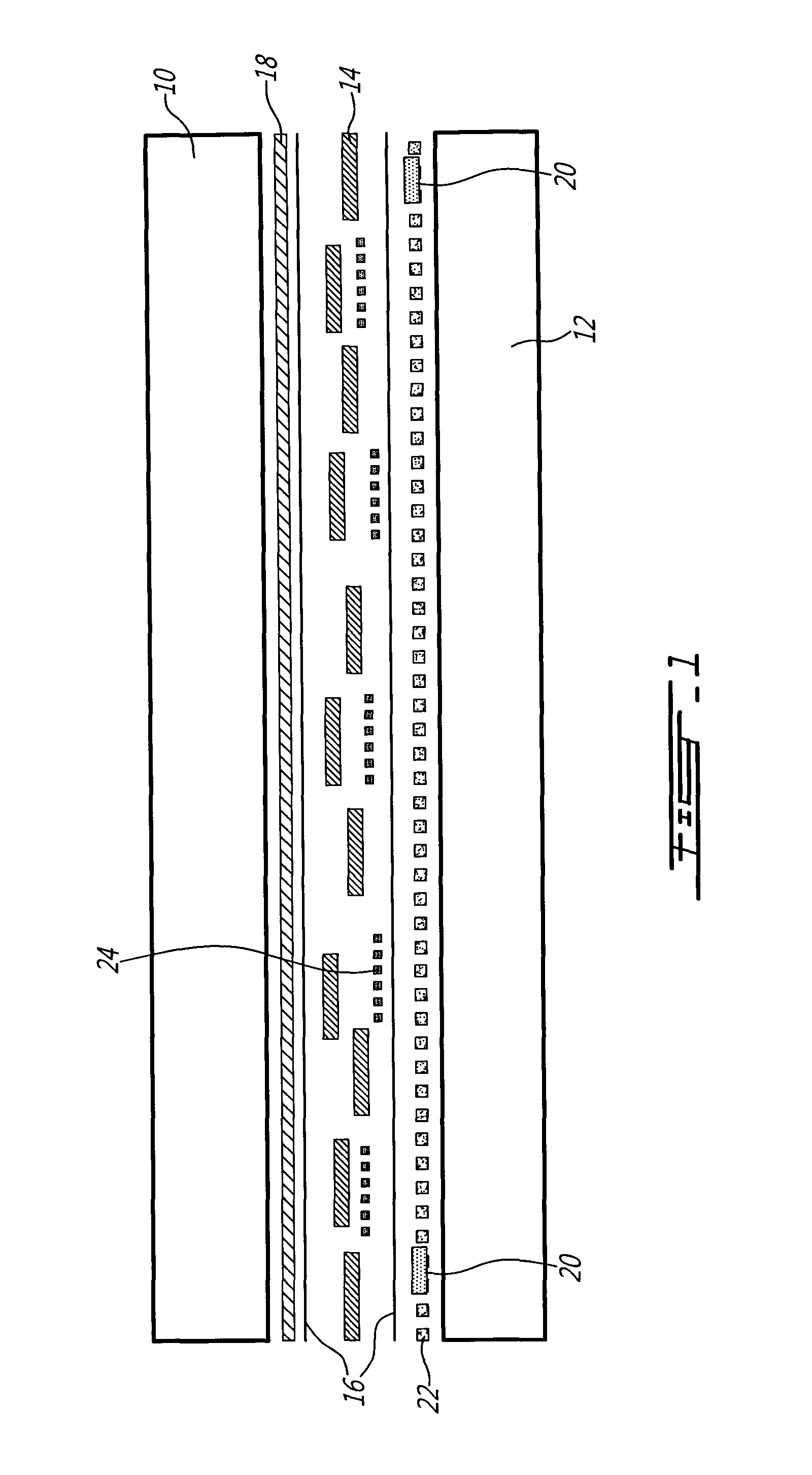
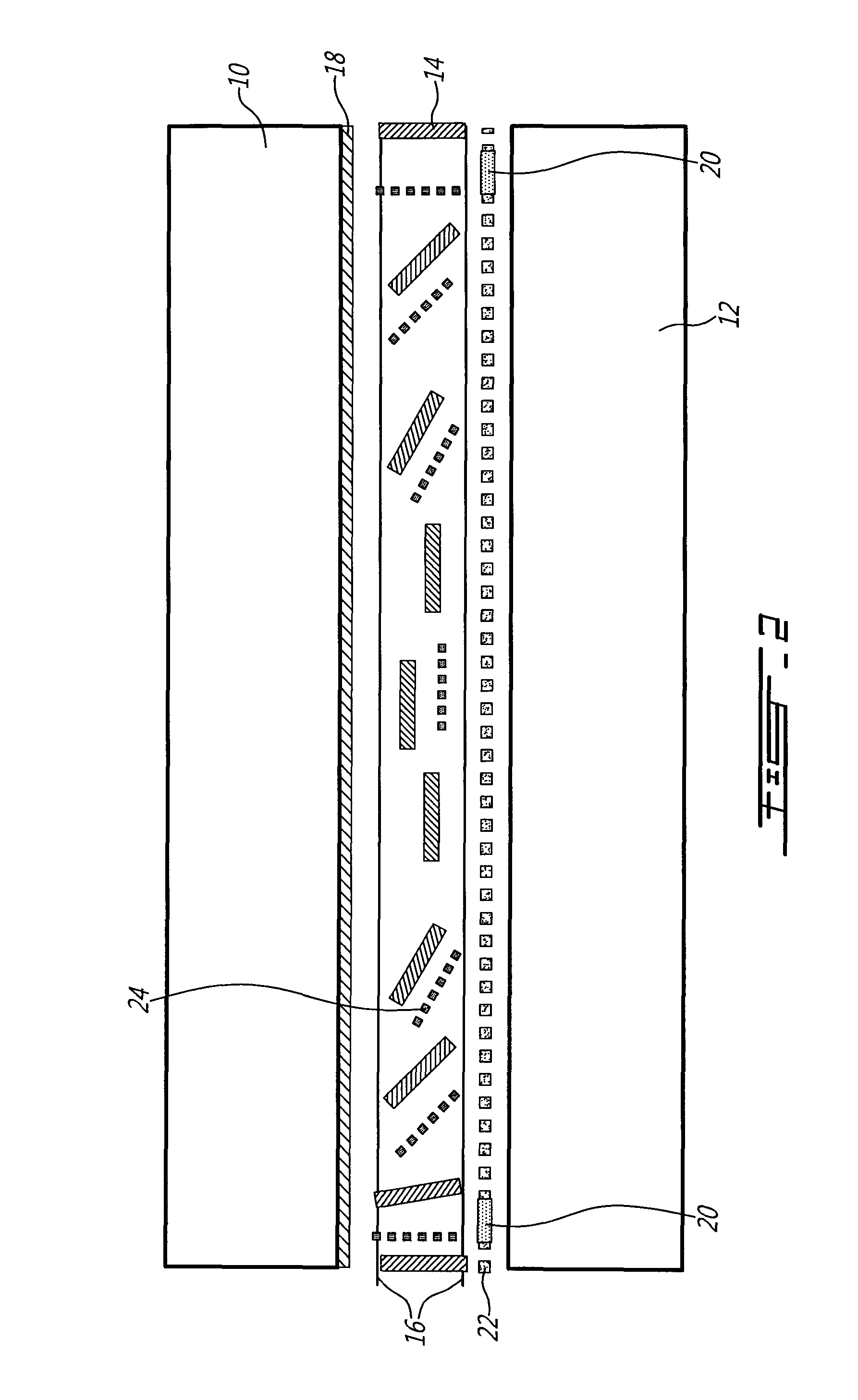
[0031]Shown in FIG. 1 is a tunable liquid crystal (LC) device according to the present invention. The structure has a top substrate 10 and a bottom substrate 12 in between which is located a LC layer 14. As is known in the art, alignment layers 16 to either side of the LC layer are used to provide the liquid crystals in the layer with a uniform alignment and pre-tilt, such that they all rotate in the same direction under the influence of an external electric field. In the present embodiment, an electric field is provided across the LC layer 14 using two optically transparent electrodes, a uniform electrode layer 18 positioned adjacent to top substrate 10, and a hole-patterned electrode 20 positioned adjacent to the bottom substrate 12. Also provided is a layer 22 of frequency dependent material (such as a high dielectric constant, high resistivity or weakly conductive material) that is also optically transparent, and that, in combination with the whole structure of the device (subst...


PUM

PropertyMeasurementUnit
angleaaaaaaaaaa
areaaaaaaaaaaa
electric fieldaaaaaaaaaa

Abstract

An apparatus for controlling light transmission from an optical input to an optical output can function as a tunable iris or eclipse, or as a privacy window. The iris / eclipse can use a liquid crystal matrix with a dispersion of dichroic particles that absorb light in one orientation and transmit light in another, such that controlling the liquid crystal with an electric field allows control of the dichroic particles. Alternatively, a layer may be used with a light absorbing liquid or powder material that moves with a charged material in response to a variable electric field applied to the layer. Privacy windows use a plurality of liquid crystal microlenses that can be controlled with an electric field to allow an image of an optical input to be obtainable at an optical output when in a first state, or to render the image irretrievable when in a second state.

Description

FIELD OF THE INVENTION[0001]This invention relates to the field of electrically controllable optical devices, particularly those using liquid crystal.BACKGROUND OF THE INVENTION[0002]Adjustable optical diaphragms and optical shutters are known in the art, and make use of mechanical components that open and close to change the amount of light allowed to pass from an input side to an output side. A tunable iris and shutter has also been shown in which a liquid crystal (LC) cell is used between two polarizers. While the tunable shutter is a rather straightforward solution (where one LC cell with two uniform electrodes is positioned between two cross oriented polarizers), the tunable iris was a similar solution but with one of electrodes being of hole patterned form. In addition, certain electrowetting liquid lenses have been used in the past to form tunable light shutters. However, each of these techniques has drawbacks such as a high loss of light (due to the use of two polarizers), a...

Claims


Application Information

Patent Timeline
Patent Type & Authority Applications(United States)
IPC IPC(8): G02F1/1333
CPCG02F1/134309G02F1/13475G02F1/13725G02F1/172G02B3/0006G02F1/13471G02F1/1337G02F1/133512G02F1/1313G02B5/09G02B3/14G02F1/13439
Inventor GALSTIAN, TIGRAN
Owner POINT FINANCIAL
Why Eureka
Try Eureka