Image processing system and image processing control apparatus

Inactive Publication Date: 2012-09-27
KONICA MINOLTA BUSINESS TECH INC
View PDF4 Cites 6 Cited by
  • Summary
  • Abstract
  • Description
  • Claims
  • Application Information

AI Technical Summary

Benefits of technology

[0008]The present invention is made in order to solve the problem described above. An object of the present invention is to provide an image processing system and an image processing control apparatus capable of reducing the power consumption in performing RIP of a print job in a distributed manner by a plurality of image processing apparatuses.

Problems solved by technology

However, as to the image processing system that performs RIP of a print job in a distributed manner by a plurality of image processing apparatuses, no attempt of power saving has been tried so far.
Since each image processing apparatus is equipped with hardware devices such as CPU (Central Processing Unit), an image processing system having a plurality of image processing apparatus consumes a substantial amount of electric power simply by keeping each image processing apparatus on a standby condition without performing RIP.

Method used


Image

  • Image processing system and image processing control apparatus
  • Image processing system and image processing control apparatus
  • Image processing system and image processing control apparatus

Examples


first embodiment

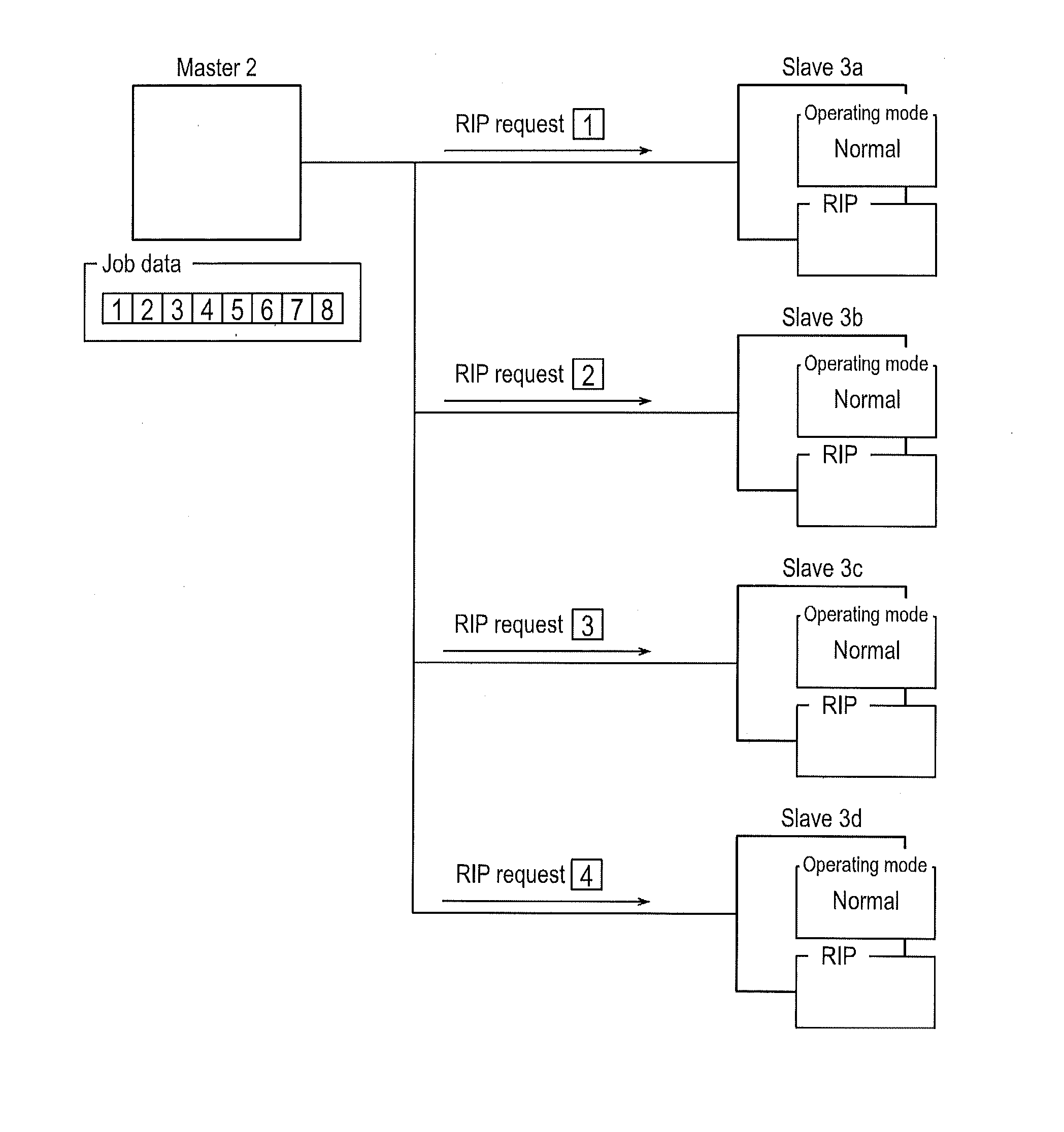
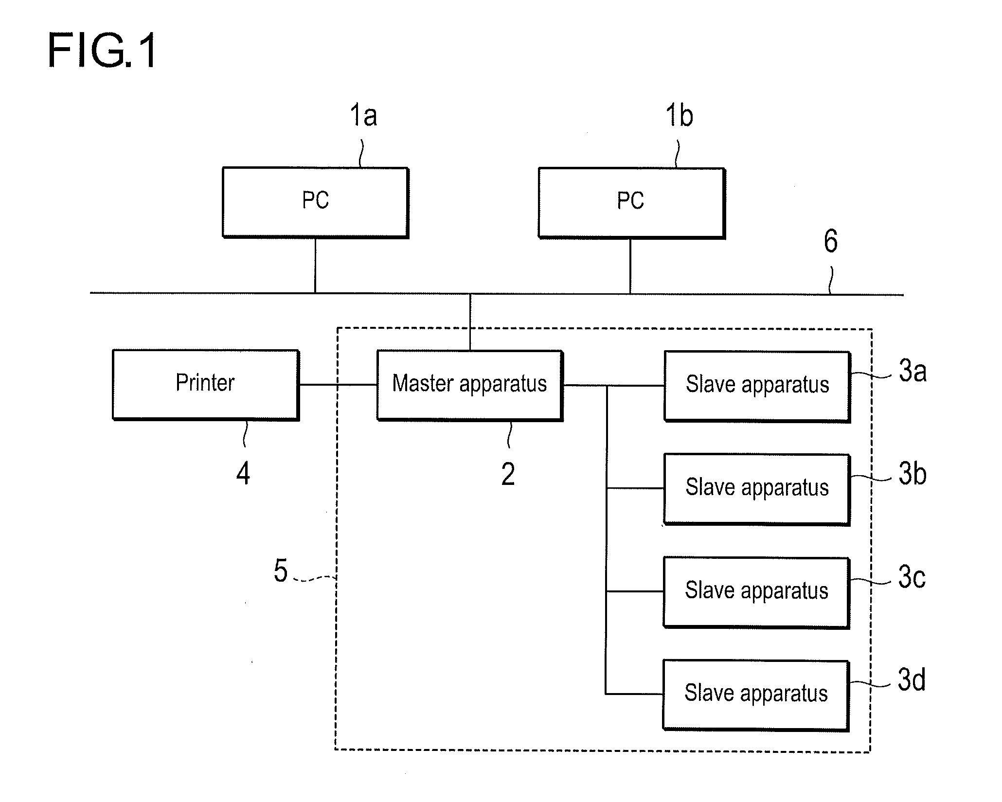
[0030]FIG. 1 is a block diagram showing the overall configuration of an image forming system according to a first embodiment of the present invention.

[0031]The image forming system according to the present embodiment has PCs (personal computers) 1a, 1b as client apparatuses, a printer controller 5 as an image processing system, and a printer 4 as an image forming apparatus. The PCs 1a, 1b and the printer controller 5 are connected to communicate with each other via a network 6. The network 6 consists of a LAN (Local Area Network) that connects computers and network equipment with each other based on standards such as Ethernet, TokenRing, and FDDI (Fiber Distributed Data Interface), or a WAN (Wide Area Network) that connects LANs via dedicated lines, etc. The printer controller 5 is a blade server equipped with a master apparatus 2 and a plurality of slave apparatuses 3a-3d. The master apparatus 2 and the plurality of slave apparatuses 3a-3d are connected to communicate with each oth...

second embodiment

[0059]In the first embodiment, a case where the total number of pages (last page) of the print job is recognized by the master apparatus was described. In the present embodiment, a case where the total number of pages of the print job is not recognized by the master apparatus will be described. For example, if the communication between the PC 1a and the printer controller 5 is temporarily suspended due to a certain communication problem, the distributed process is initiated without recognizing the total number of pages of the print job by the master apparatus 2. In the present embodiment wherein the distributed process is executed without recognizing the total number of pages of the print job, the operating mode of the slave apparatus is switched in accordance with the number of pages of the image data waiting to be printed. Since the configuration of the image forming system of the present embodiment is identical to that of the first embodiment other than the fact that the operatin...

third embodiment

[0103]The third embodiment of the present invention will be described below with reference to FIGS. 16 and 17. The present embodiment is an embodiment wherein the RIP of one page is performed by one slave apparatus each time the printing output of one page is completed, when the number of remaining pages exceeds the threshold value. The slave apparatus of the present embodiment is configured to switch to the power saving mode automatically when it does not receive a RIP instruction from the master apparatus.

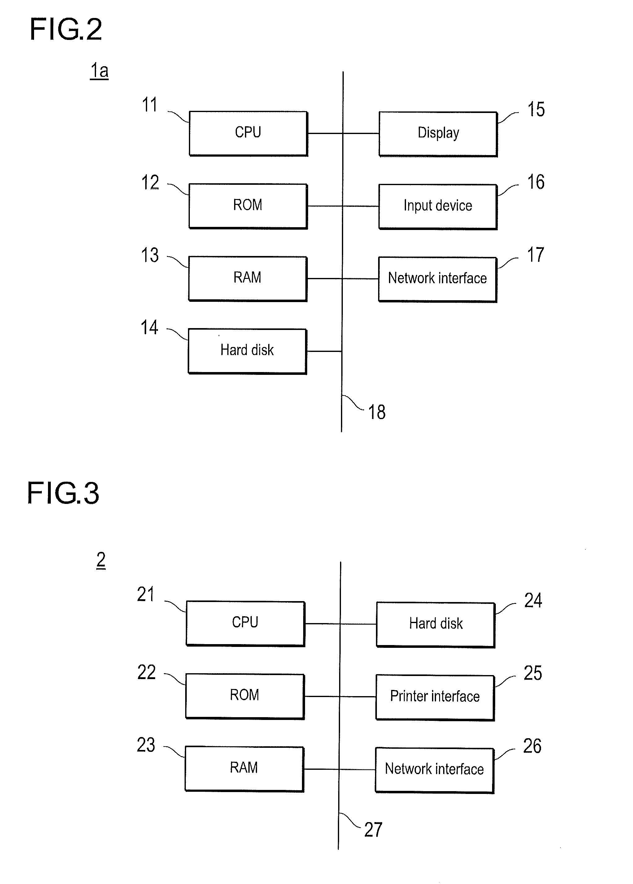
[0104]FIG. 16 is a flowchart showing the procedure of the distributed process according to the third embodiment of the present invention. The algorithm shown in the flowchart of FIG. 16 is stored as a program in the hard disk 24 of the master apparatus 2 and is executed by the CPU 21.

[0105]First, upon receiving the print job, the performance of the RIP is instructed to all the slave apparatuses 3a-3d (steps S501, S502).

[0106]Next, a judgment is made as to whether or not the RIP c...


PUM


Abstract

An image processing system has a plurality of image processing apparatuses for performing RIP of a print job in a distributed manner and an image processing control apparatus that controls the image processing apparatuses. The image processing apparatus has a switching unit for switching the operating mode of the image processing apparatus from a normal mode to a power saving mode. And the image processing control apparatus has a control unit for causing unnecessary image processing apparatuses to switch from the normal mode to the power saving mode depending on the progress status of the print job.

Description

CROSS-REFERENCE TO RELATED APPLICATION[0001]This application is based on Japanese Patent Application No. 2011-068696 filed on Mar. 25, 2011, the contents of which are incorporated herein by reference.BACKGROUND[0002]1. Technical Field[0003]The present invention relates to an image processing system and an image processing control apparatus for performing raster image processing of a print job in a distributed manner by a plurality of image processing apparatuses.[0004]2. Description of Related Art[0005]An image processing system that performs raster image processing (hereinafter referred to as “RIP”) of a print job in a distributed manner by a plurality of image processing apparatuses is known (e.g., Unexamined Japanese Patent Publication No. 2009-214348). According to such an image processing system, one print job is split by page and the RIP of each page is performed in parallel by a plurality of image processing apparatuses so that the time required for the RIP of the print job i...

Claims


Application Information

Patent Timeline
IPC IPC(8): G06F3/12
CPCG06F1/3284G06F3/1221G06F3/1229G06F3/1286Y02B60/32H04N1/00904H04N2201/0094Y02B60/1271Y02B60/1267H04N1/00896Y02D10/00Y02D30/50
Inventor KAMEI, TASUKU
Owner KONICA MINOLTA BUSINESS TECH INC
Why Eureka
Try Eureka