
Illumination system

a technology of illumination system and light source, which is applied in the direction of instruments, lighting and heating apparatus, optical elements, etc., can solve the problems of divergent light, not completely replacing the conventional high-pressure mercury lamp, and still inferior solid-state light sources to the extent of luminance they provide, so as to improve the luminance and simple construction

Active Publication Date: 2012-09-27
DELTA ELECTRONICS INC
View PDF5 Cites 39 Cited by
  • Summary
  • Abstract
  • Description
  • Claims
  • Application Information

AI Technical Summary

Benefits of technology

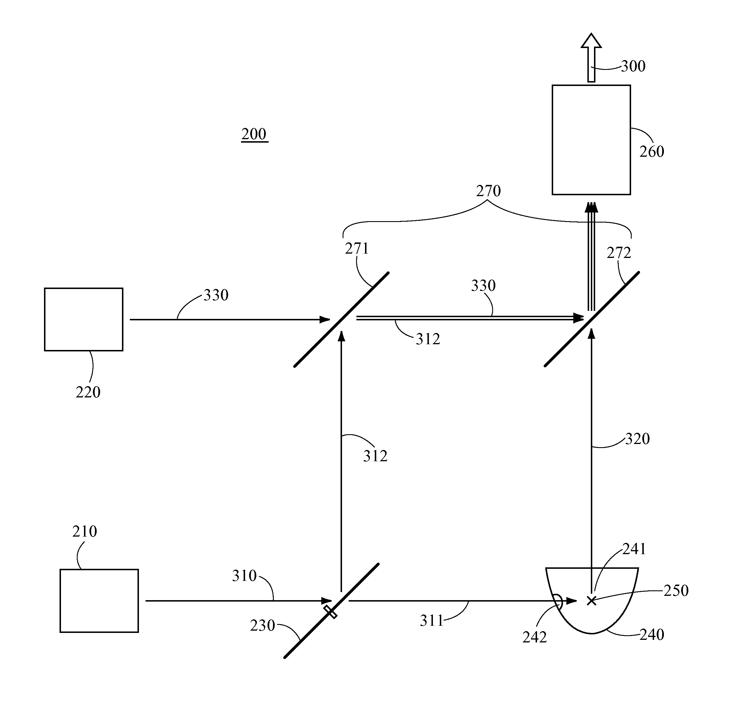
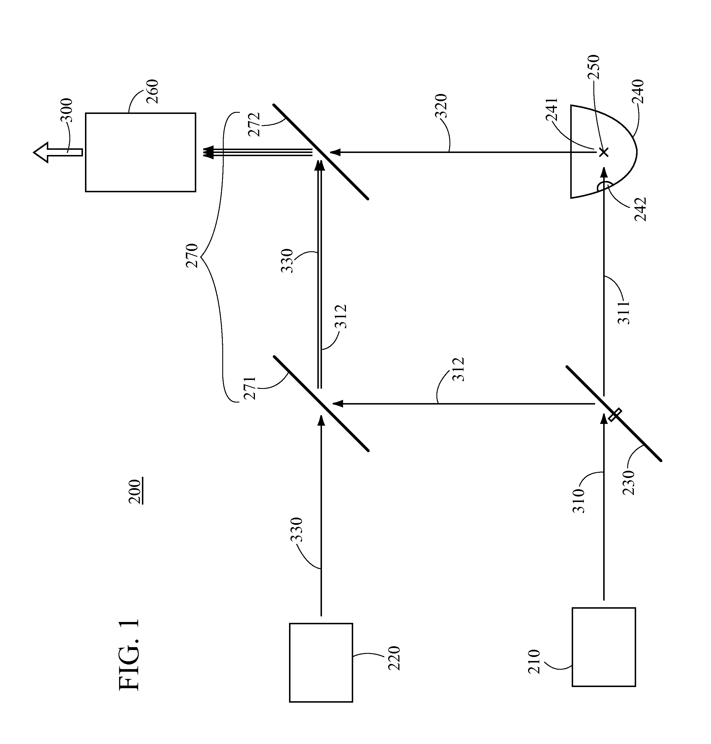
[0013]To achieve the aforesaid objective, the illumination system of the present invention comprises a first light source, a first timing controlling unit, a curved reflecting component and a wavelength converting component. The first light source provides a first wavelength light, while the first timing controlling unit divides the first wavelength light into a first timing portion and a second timing portion. The curved reflecting component has a focal point, while the wavelength converting component is disposed at the focal point for converting the first timing portion of the first wavelength light into a second wavelength light and then emitting the second wavelength light in a convergent manner, thereby achieving the advantages of concentrating the light and improving the luminance.
[0014]Another objective of the present invention is to provide an illumination system for a projector, which has a simple construction and can generate concentrated light of different wavelengths.

Problems solved by technology

However, when being used as light sources for projectors, solid state light sources are still inferior to conventional high-pressure mercury lamps in terms of the luminance they provide.
Therefore, although the solid state light sources are used more widely, they have not yet completely replaced the conventional high-pressure mercury lamps in the field of projection apparatuses.
However, although the aforesaid two approaches can use the light beams emitted by the solid state light sources to form the red, blue and green light (and optionally, a yellow light) for light coupling purposes, both the aforesaid approaches result in divergent light and suffer from low efficiency due to limitations of inherent optical properties of the light sources.
In particular for the second approach, the blue light for exciting the green phosphor cannot be fully converted into the green light and the blue light must be recycled by the reflecting mirrors from behind, which makes the optical path of the blue light elongated; consequently, this light coupling approach fails to provide an effective solution in terms of the blue light and the green light that is generated through excitation.
Therefore, the light coupling approaches of the prior art not only provide a limited effect in improving the efficiency of generating the green light, but also increase the volume, weight and manufacturing cost of the overall system due to the use of reflecting mirrors, which makes the related products uncompetitive in the market.

Method used


Image

  • Illumination system
  • Illumination system
  • Illumination system

Examples


first embodiment

[0037]an illumination system 200 for a projector according to the present invention is shown in FIG. 1. The illumination system 200 comprises a first light source 210, a second light source 220, a first timing controlling unit 230, a curved reflecting component 240, a wavelength converting component 250, a light homogenizing component 260 and at least one color separating mirror (i.e. a dichroic mirror) 270. The first light source 210 is adapted to provide a first wavelength light 310, while the second light source 220 is adapted to provide a third wavelength light 330. Meanwhile, the first timing controlling unit 230 is adapted to divide the first wavelength light 310 into a first timing portion 311 and a second timing portion 312. The wavelength converting component 250 is disposed at a focal point 241 of the curved reflecting component 240 so that when the wavelength converting component 250 receives the first timing portion 311 of the first wavelength light 310, the first timing...

second embodiment

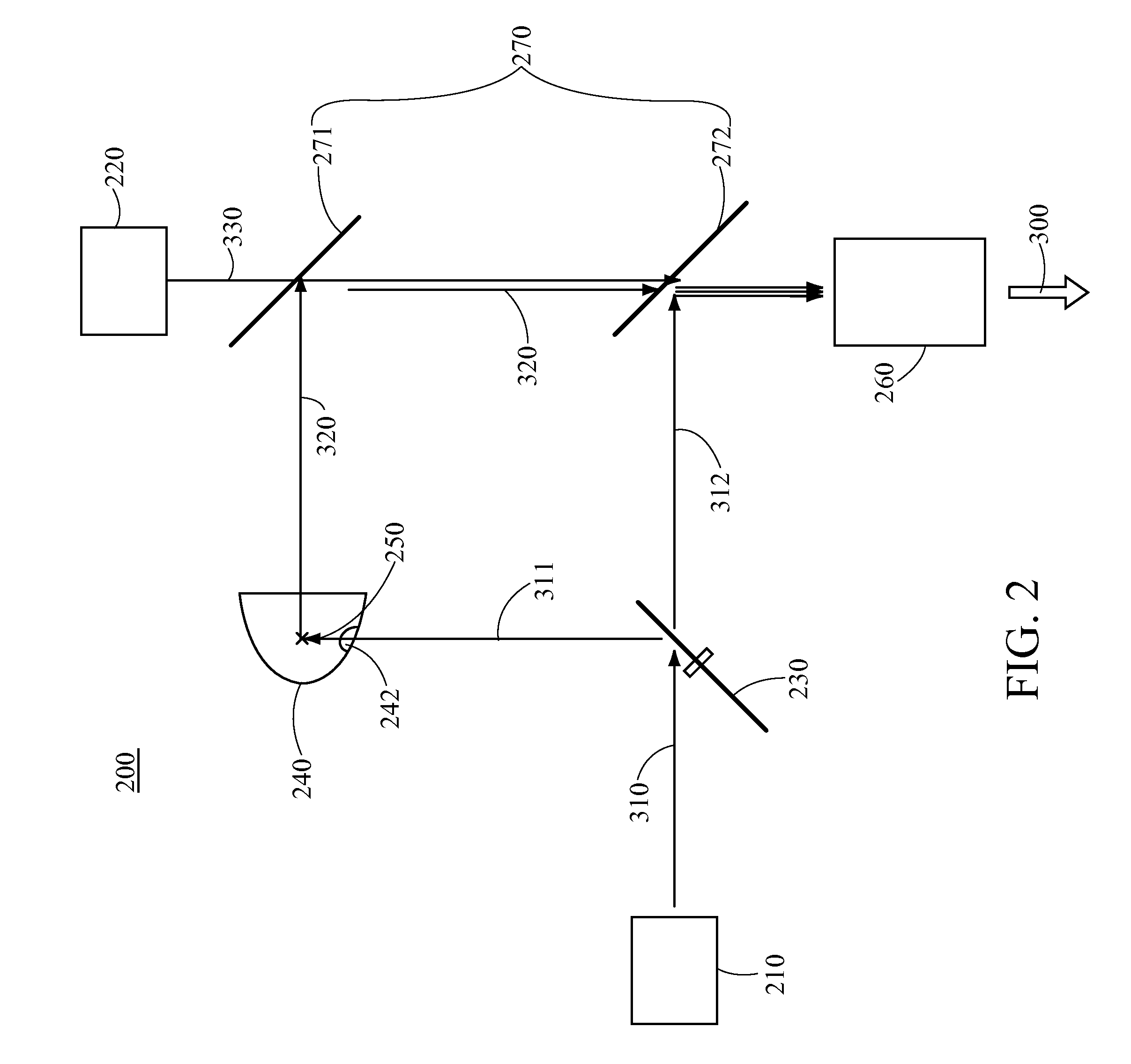
[0048]The traveling paths of the first wavelength light 310, the second wavelength light 320 and the third wavelength light 330 in the second embodiment will be described as follows. As shown in FIG. 2, when the first wavelength light 310 is emitted by the first light source 210, the first timing portion 311 of the first wavelength light 310 is reflected by the reflecting portions 232 of the first timing controlling unit 230 and then passes through the hole 242 formed in the curved reflecting component 240 to the wavelength converting component 250 located at the focal point 241 of the curved reflecting component 240. The wavelength converting component 250 converts the first timing portion 311 of the first wavelength light 310 into the second wavelength light 320, which is then reflected and converged by the curved reflecting component 240 to the first color separating mirror 271. Then, the second wavelength light 320 is reflected by the first color separating mirror 271, and is tr...

third embodiment

[0051]In detail, the second timing controlling unit 400 comprised in the third embodiment is adapted to divide the first timing portion 311 of the received first wavelength light 310 into a third timing portion (not shown) and a fourth timing portion (not shown); the third timing portion has the same timing as the second timing portion 312. The second timing controlling unit 400 comprises a rotary disk 410 that is rotatable, and the direction of the rotation axis of the rotary disk 410 may be perpendicular to the direction of exiting light from the curved reflecting component 280.

[0052]The rotary disk 410 has at least one converting portion (or converting region) and at least one reflecting portion (or reflecting region). As shown in FIG. 5, in this embodiment, the rotary disk 410 preferably has two converting portions 411 and two reflecting portions 412 on each of the two surfaces thereof, and the two converting portions 411 are arranged alternately with the two reflecting portions...


PUM


Abstract

An illumination system for use in a projector is provided. The illumination system comprises a first light source, a first timing controlling unit, a curved reflecting component and a wavelength converting component. The first light source provides a first wavelength light, while the first timing controlling unit divides the first wavelength light into a first timing portion and a second timing portion. The curved reflecting component comprises a focal point. The wavelength converting component is disposed at the focal point for converting the first timing portion of the first wavelength light into a second wavelength light.

Description

[0001]This application claims priority of an U.S. Provisional Patent Application No. 61 / 466,504 filed on Mar. 23, 2011, which is entirely incorporated herein by reference.BACKGROUND OF THE INVENTION[0002]1. Field of the Invention[0003]The present invention relates to an illumination system, and more particularly, to an illumination system for a projector.[0004]2. Descriptions of the Related Art[0005]Solid state light sources such as light emitting diodes (LEDs) or lasers have a long service life, a small volume and mercury-free. However, when being used as light sources for projectors, solid state light sources are still inferior to conventional high-pressure mercury lamps in terms of the luminance they provide. Therefore, although the solid state light sources are used more widely, they have not yet completely replaced the conventional high-pressure mercury lamps in the field of projection apparatuses.[0006]On the other hand, to enable a light source in a projector to uniformly pro...

Claims


Application Information

Patent Timeline
IPC IPC(8): F21V9/16F21V7/00G02B7/00
CPCH04N9/3164G03B21/2066G03B21/204G03B33/08H04N9/3111
Inventor LIN, HUNG-YING
Owner DELTA ELECTRONICS INC
Learn More