Power Supply Device

a power supply device and power supply technology, applied in the direction of dc-dc conversion, power conversion systems, climate sustainability, etc., can solve the problems of another device, and achieve the effects of reducing emi noise, shortening pulse width, and reducing emi nois

Active Publication Date: 2012-09-27
HITACHI LTD
View PDF5 Cites 22 Cited by
  • Summary
  • Abstract
  • Description
  • Claims
  • Application Information

AI Technical Summary

Benefits of technology

[0018]The switching control device includes a pulse position modulation circuit that modulates a pulse position; a pulse width modulation circuit that modulates a pulse width; and a pulse generator circuit that generates a pulse modulated by the pulse position modulation circuit and the pulse width modulation circuit. When a pulse interval of the pulse modulated in the pulse position by the pulse position modulation circuit is sparser than the pulse interval of the pulse before the modulation, the pulse width modulation circuit lengthens the pulse width. On the contrary, when the pulse interval of the pulse modulated in the pulse position by the pulse position modulation circuit is denser than the pulse interval of the pulse before the modulation, the pulse width modulation circuit shortens the pulse width.
[0020]That is, the typical advantage resides in that there can be provided the power supply device that performs both of the suppression of the EMI noise and the reduction in the ripple of the output voltage.

Problems solved by technology

The switching power supply causes intense electro-magnetic interference (EMI) to be generated with the switching operation, and therefore may incur drawbacks such as malfunction or breakdown of another device as a noise generator source.

Method used


Image

  • Power Supply Device
  • Power Supply Device
  • Power Supply Device

Examples


first embodiment

[0056]As a power supply device according to a first embodiment of the present invention, a switching power supply that controls a switch according to a control signal to generate a supply voltage will be exemplified with reference to FIGS. 1 to 4.

Configuration of Switching Power Supply

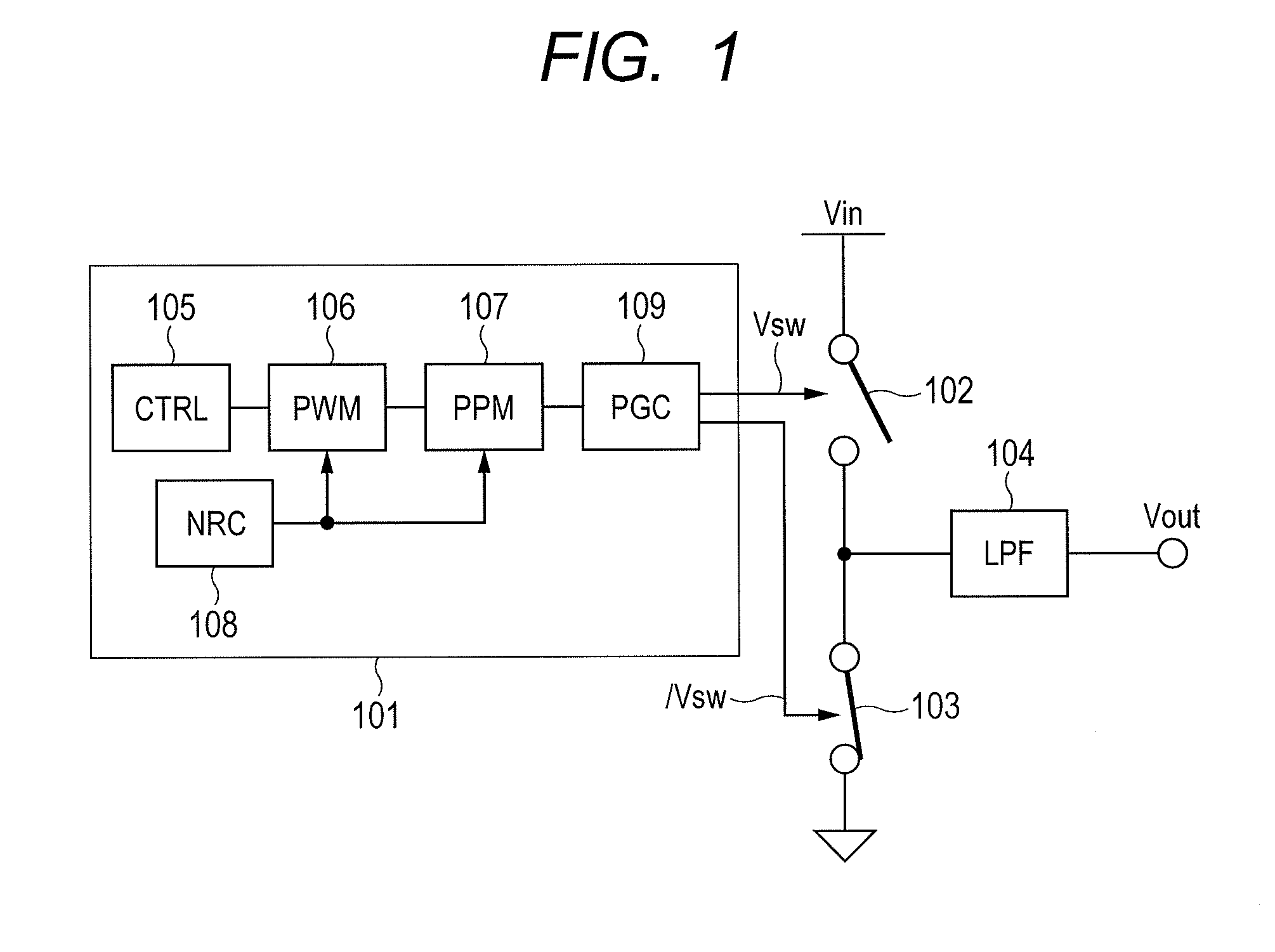
[0057]FIG. 1 illustrates an example of a configuration of a switching power supply according to this embodiment. This embodiment shows an example of a DC-DC converter that steps down an input voltage Vin to obtain an output voltage Vout.

[0058]The switching power supply according to this embodiment includes a switching control device 101, switches 102 and 103 that are controlled by the switching control device 101, and connected in series between the input voltage Vin and a ground, and a low-pass filter (LPF) 104 that is connected to a connection point of the switches 102 and 103. The switching control device 101 includes a controller (CTRL) 105, a PWM circuit (PWM) 106 that is connected to the controll...

second embodiment

[0072]A switching power supply according to a second embodiment of the present invention will be described with reference to FIG. 5. In this embodiment, a description will be given of a case in which a technique of the noise diffusion and the ripple suppression according to the present invention is applied to the switching power supply that conducts the feedback control.

[0073]FIG. 5 illustrates an example of a configuration of the switching power supply according to this embodiment. The switching power supply according to this embodiment includes a switching control device 501, the switches 102 and 103, and the low-pass filter 104. The switching control device 501 includes a differential circuit 502 to which the output voltage Vout is fed back, a controller 503 that is connected to the differential circuit 502, the PWM circuit 106 that is connected to the controller 503, the PPM circuit 107 that is connected to the PWM circuit 106, the noise ripple controller 108 that is connected t...

third embodiment

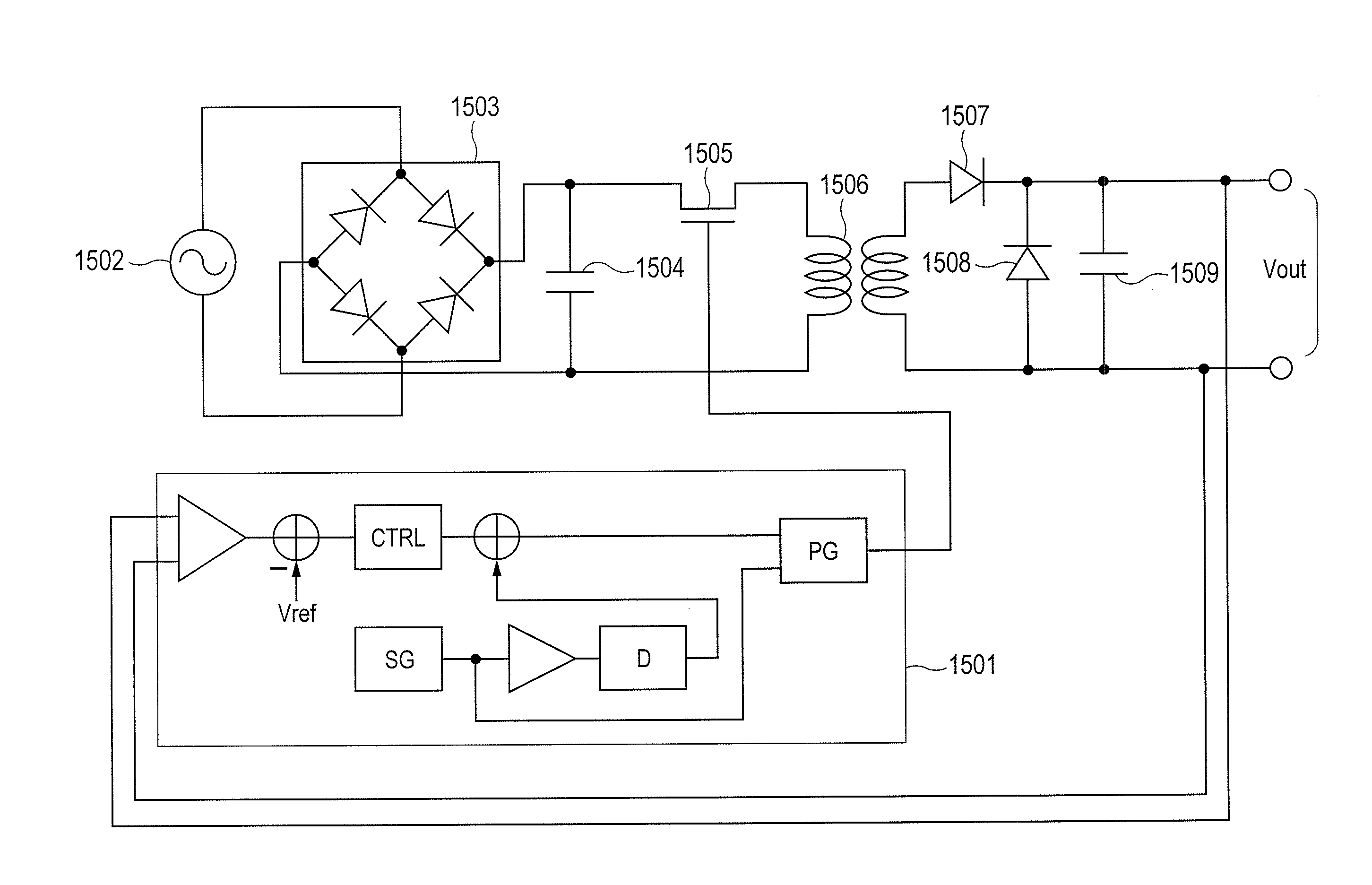
[0077]A switching power supply according to the present invention will be described with reference to FIGS. 6 and 7. This embodiment exemplifies a more specific configuration of the switching power supply.

[0078]FIG. 6 illustrates an example of a configuration of the switching power supply according to this embodiment. The switching power supply according to this embodiment includes a switching control device 601, the switches 102 and 103, and the low-pass filter 104. The switching control device 601 includes the differential circuit 502 to which the output voltage Vout is fed back, the controller 503 that is connected to the differential circuit 502, a signal generator (SG) 602, an amplifier 603 that is connected to the signal generator 602, a phase regulator (D) 604 that is connected to the amplifier 603, an adder 605 that is connected to the controller 503 and the phase regulator 604, and a pulse generator (PG) 606 that is connected to the adder 605 and the signal generator 602. T...


PUM


Abstract

A power supplying device performs both of a suppression of EMI noise and a reduction in an output voltage. In the power supply device, a switching control device that controls a switching element according to a pulse control signal includes a PPM circuit that modulates a pulse position; a PWM circuit that modulates a pulse width; and a pulse generator circuit that generates a pulse modulated by the PPM circuit and the PWM circuit. When a pulse interval of the pulse modulated in the pulse position by the PPM circuit is sparser than the pulse interval of the pulse before the modulation, the PWM circuit lengthens the pulse width. On the contrary, when the pulse interval of the pulse modulated in the pulse position by the PPM circuit is denser than the pulse interval of the pulse before the modulation, the PWM circuit shortens the pulse width.

Description

CLAIM OF PRIORITY[0001]The present application claims priority from Japanese patent application JP 2011-065231 filed on Mar. 24, 2011, the content of which is hereby incorporated by reference into this application.FIELD OF THE INVENTION[0002]The present invention relates to a power supply device, and more particularly to a technology effectively applied to a switching power supply that generates supply voltage while controlling a switch according to a control signal.BACKGROUND OF THE INVENTION[0003]A switching power supply is high in power conversion efficiency, smaller in size and lighter in weight than a power capacity, and low in the costs, and therefore has been widely employed from a small-capacity power supply to a large-capacity power supply. There have been known switching power supplies such as an AC-DC converter that converts an AC power from an AC power supply into a DC power supply, a DC-DC converter that steps down or up a voltage of the DC power to obtain another DC po...

Claims


Application Information

Patent Timeline
Patent Type & Authority Applications(United States)
IPC IPC(8): H02M1/14H02M3/335G05F1/10
CPCH02M3/156Y02B70/1466H02M7/53803H02M3/1588Y02B70/10
Inventor NAKAGAWA, TATSUO
Owner HITACHI LTD
Why Eureka
Try Eureka