Emergency core cooling system for pressurized water reactor

Active Publication Date: 2012-09-27
BWXT MPOWER INC
View PDF3 Cites 34 Cited by
  • Summary
  • Abstract
  • Description
  • Claims
  • Application Information

AI Technical Summary

Benefits of technology

[0012]In another aspect of the disclosure, an apparatus comprises: a PWR including a pressure vessel containing a nuclear reactor core and primary coolant water, the pressure vessel defining an internal pressurizer volume containing a steam bubble and having at least one steam pressure control device; a containment structure surrounding the PWR; an external heat sink disposed outside of the containment structure; at least one condenser disposed inside the containment structure and operatively connected

Problems solved by technology

In various abnormal event scenarios, this radioactivity can increase rapidly, potentially leading in turn to rapid and uncontrolled increase in primary coolant pressure and temperature.
For example, in a “loss of heat sink event” the secondary coolant flow in the steam generator fails, leading to loss of heat sinking provided by the secondary coolant.
In a scram failure, the control rod system is compromised such that the control rods may be unable to “scram”, that is, be released to fall into the reactor core, to provide rapid shutdown.
While a scram failure may not cause immediate core heating, the loss

Method used


Image

  • Emergency core cooling system for pressurized water reactor
  • Emergency core cooling system for pressurized water reactor
  • Emergency core cooling system for pressurized water reactor

Examples


Embodiment Construction

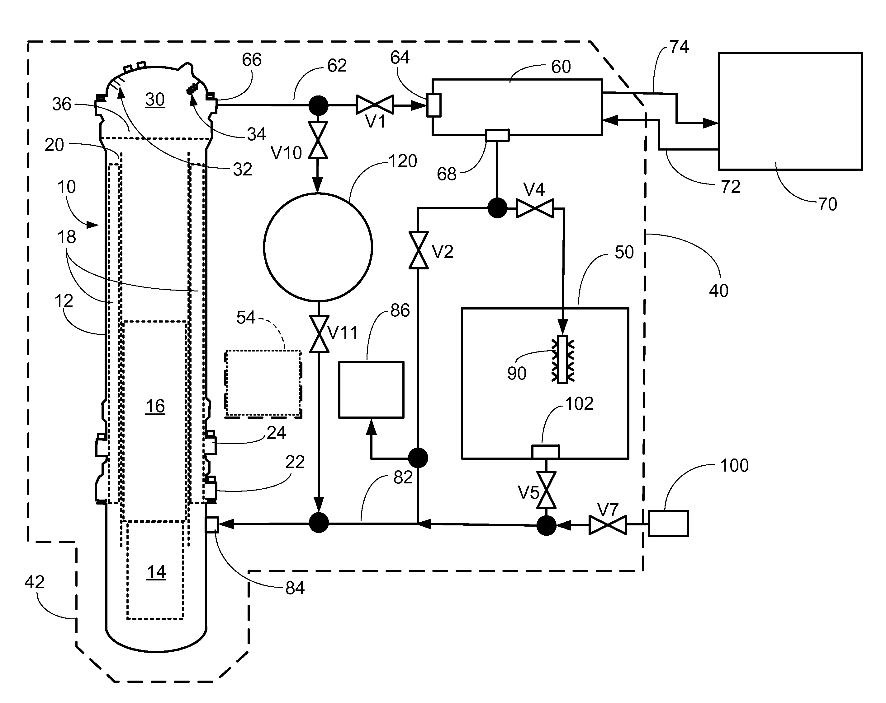
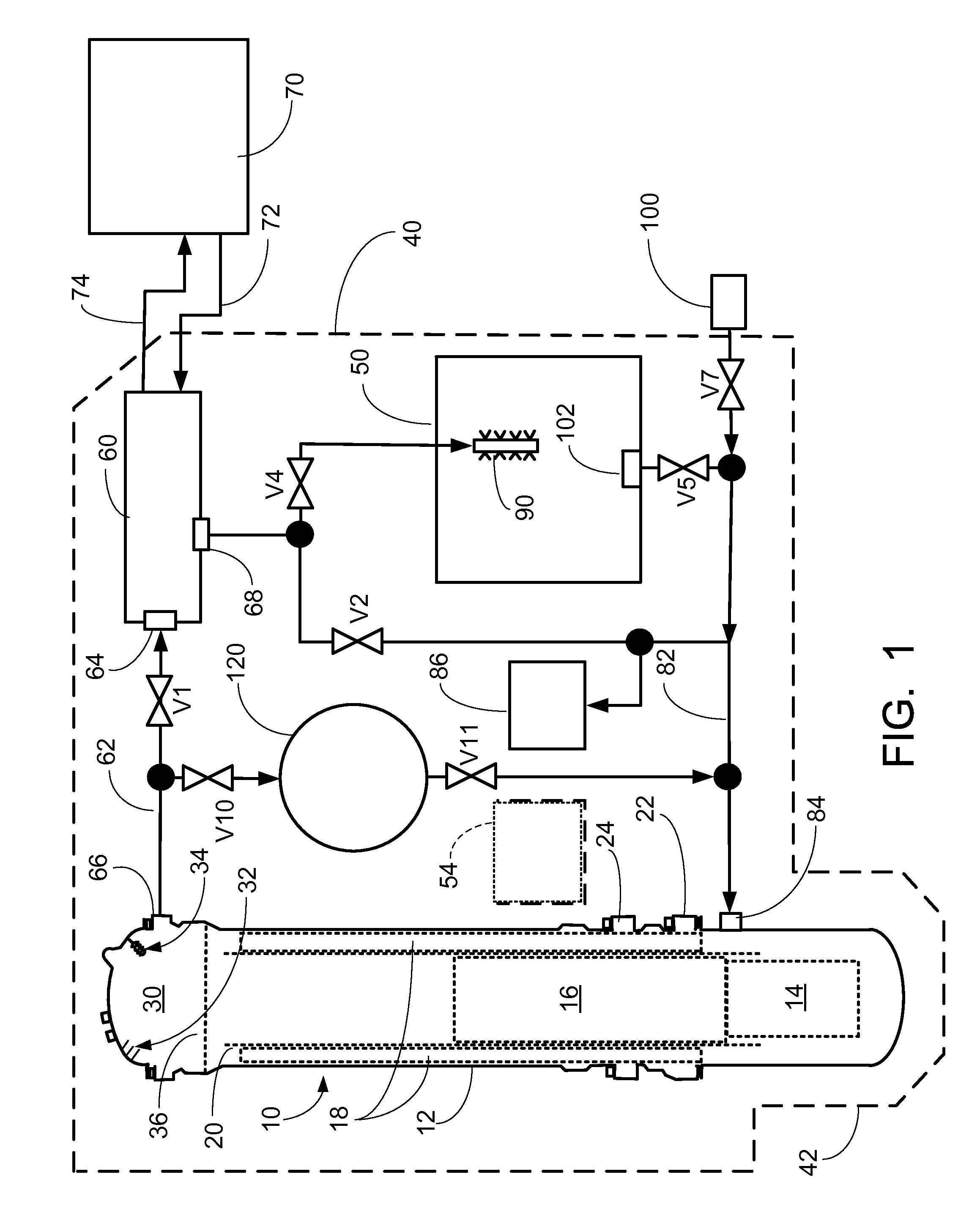
[0016]With reference to FIG. 1, an illustrative nuclear reactor of the pressurized water reactor (PWR) type 10 includes a pressure vessel 12, which in the illustrative embodiment is a generally cylindrical vertically mounted vessel. Selected components of the PWR that are internal to the pressure vessel 12 are shown diagrammatically in phantom (that is, by dotted lines). A nuclear reactor core 14 is disposed in a lower portion of the pressure vessel 12. The reactor core 14 includes a mass of fissile material, such as a material containing uranium oxide (UO2) that is enriched in the fissile 235U isotope, in a suitable matrix material. In a typical configuration, the fissile material is arranged as “fuel rods” arranged in a core basket. The pressure vessel 12 contains primary coolant water (typically light water, that is, H2O, although heavy water, that is, D2O, is also contemplated) in a subcooled state.

[0017]A control rod system 16 is mounted above the reactor core 14 and includes c...


PUM


Abstract

A pressurized water nuclear reactor (PWR) has an internal pressurizer volume containing a steam bubble and is surrounded by a containment structure. A condenser is disposed inside the containment structure and is operatively connected with an external heat sink disposed outside of the containment structure. A valve assembly operatively connects the PWR with the condenser responsive to an abnormal operation signal such that the condenser condenses steam from the steam bubble while rejecting heat to the external heat sink and returns the condensed water to the PWR. A quench tank contains water with dissolved neutron poison. A valved tank pressurizing path selectively connects the steam bubble to the quench tank to pressurize the quench tank, and a valved soluble poison delivery path selectively connects the quench tank to the PWR such that the quench tank under pressure from the steam bubble discharges water with dissolved neutron poison into the PWR.

Description

BACKGROUND[0001]The following relates to the nuclear reactor arts, electrical power generation arts, nuclear safety arts, and related arts.[0002]Nuclear reactors employ a reactor core comprising a mass of fissile material, such as a material containing uranium oxide (UO2) that is enriched in the fissile 235U isotope. Primary coolant water, such as light water (H2O) or heavy water (D2O) or some mixture thereof, flows through the reactor core to extract heat for use in heating secondary coolant water to generate steam or for some other useful purpose. For electrical power generation, the steam is used to drive a generator turbine. In thermal nuclear reactors, the primary coolant water also serves as a neutron moderator that thermalizes neutrons, which enhances reactivity of the fissile material. Various reactivity control mechanisms, such as mechanically operated control rods, chemical treatment of the primary coolant with a soluble neutron poison, or so forth are employed to regulate...

Claims


Application Information

Patent Timeline
IPC IPC(8): G21C15/18
CPCG21C15/18G21D3/06G21C9/033G21C1/32G21C9/012Y02E30/32Y02E30/30G21C9/00G21C15/00
Inventor MALLOY, JOHN D.
Owner BWXT MPOWER INC
Why Eureka
Try Eureka