Eureka AIR delivers breakthrough ideas for toughest innovation challenges, trusted by R&D personnel around the world.

Structure of paper converting machine

Inactive Publication Date: 2012-09-27
MTC MACCINE TRASFORMAZIONE CARTA SRL
View PDF0 Cites 14 Cited by
  • Summary
  • Abstract
  • Description
  • Claims
  • Application Information

AI Technical Summary

Benefits of technology

[0012]It is therefore a feature of the present invention to provide a machine structure for converting paper, or similar products, which improves the cutting phase of the web of paper, without causing the above described drawbacks.
[0013]It is still a feature of the present invention to provide a machine structure for converting paper, or similar products, which avoids to damage the web, or the sheet, during the cutting or perforation step, and then to optimize the quality of the final product, avoiding maintenance stops for removing the paper adhered to the surface of the blade.
[0017]wherein at least one of the blades comprises a plate of metal sheet having a main body and a cutting edge with a cutting profile;whose main feature is that the main body of the plate of metal sheet has at least one weakened portion arranged at a predetermined distance from the cutting edge, the or each weakened portion configured to reduce the stiffness of the plate of metal sheet in such a way that, when the first blade and the second blade contact each other, the weakened portion is configured to cause a modified resilient response that reduces contact forces between the blades and avoids that the web of paper, once cut or perforated, can adhere to the surface of the knives.
[0018]In particular, the or each weakened portion is adapted to reduce the elasticity modulus of the main body of the plate of metal sheet down to a predetermined value.
[0019]This way, it is avoided that the cut paper adhering to the surface of a blade can affect a correct cutting or perforation step, or a following transfer step downstream of the cutting or perforation section. This allows, therefore, to avoid damaging the cut web and to optimize the quality of the final product. Furthermore, it is avoided the need of a maintenance stop for removal of the web, cut or perforated, adhered to the surface of the blade.
[0034]cutting or perforating the, or each, web of paper, the cut or perforation carried out by at least one blade that operates in combination with a stationary knife to cut or perforate the web of paper, wherein the blade comprises a main body and a cutting edge with a cutting profile, the main body having at least one weakened portion arranged at a predetermined distance from the cutting edge, the, or each, weakened portion configured to reduce the stiffness of the cutting edge in order to reduce the contact forces and avoid that the web once cut can adhere to the surface of the blade.

Problems solved by technology

However, in the machines of known type, both interfolding and rewinding machines as above described, during the cutting or perforation step, owing to the high stiffness of the cutting edges and to the softness of the “tissue” paper used to make hygiene products such as napkins, toilet paper, etc., the web, or the cut sheet, can adhere to the surface of such profiles, jeopardizing the cutting or perforation step, and then the following step of conveying further the sheet or web.
In particular, if a cut sheet remains on the surface of the cutting edges it is possible that, during transfer steps, it can be torn, or in any case damaged, penalizing the quality of the final product.
Then, a product is obtained of inferior quality, with defects caused by the imperfect cutting step.
Also the solution described in WO2008 / 015588 has the above described drawback of the machines of the prior art.

Method used


Image

  • Structure of paper converting machine
  • Structure of paper converting machine
  • Structure of paper converting machine

Examples


Embodiment Construction

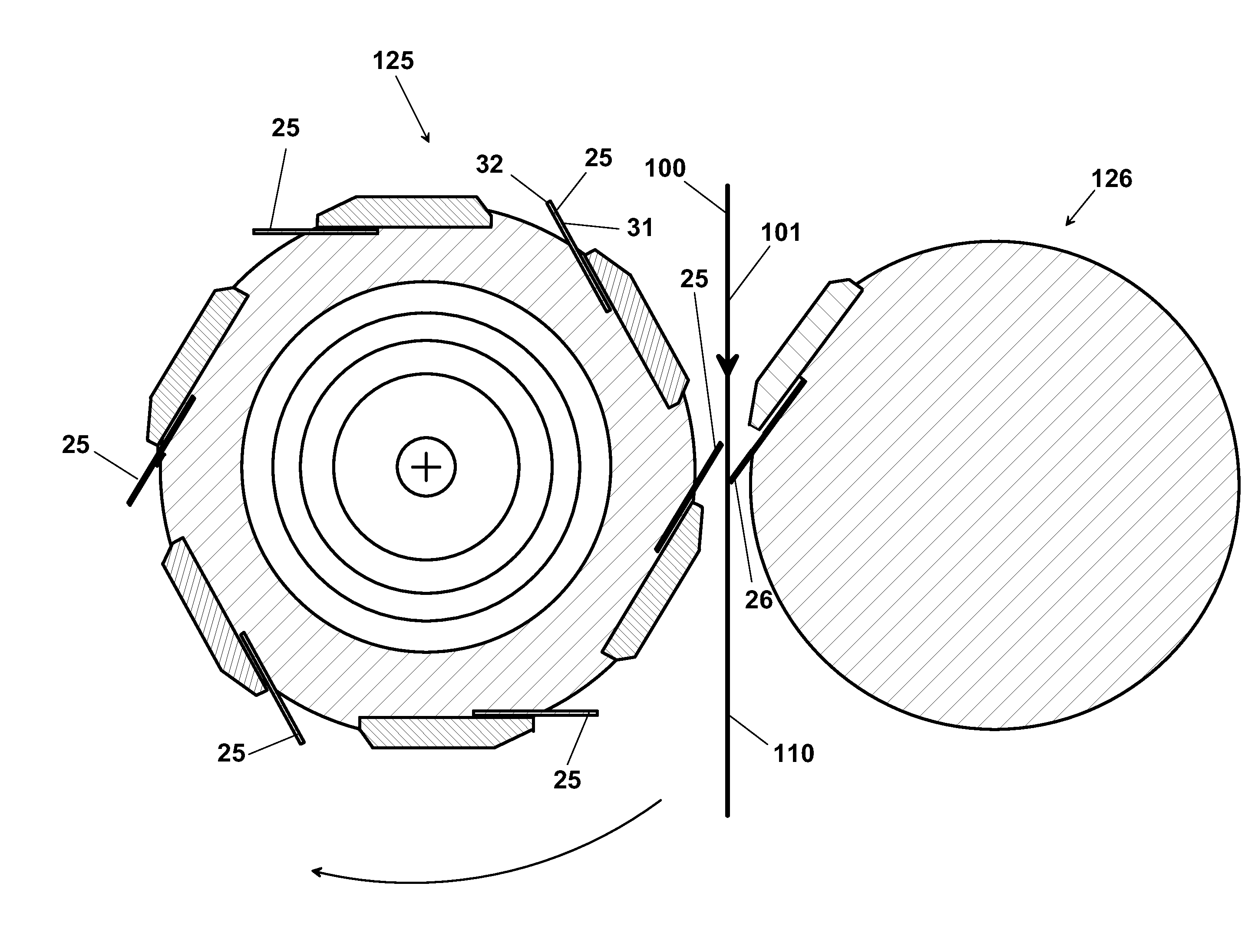
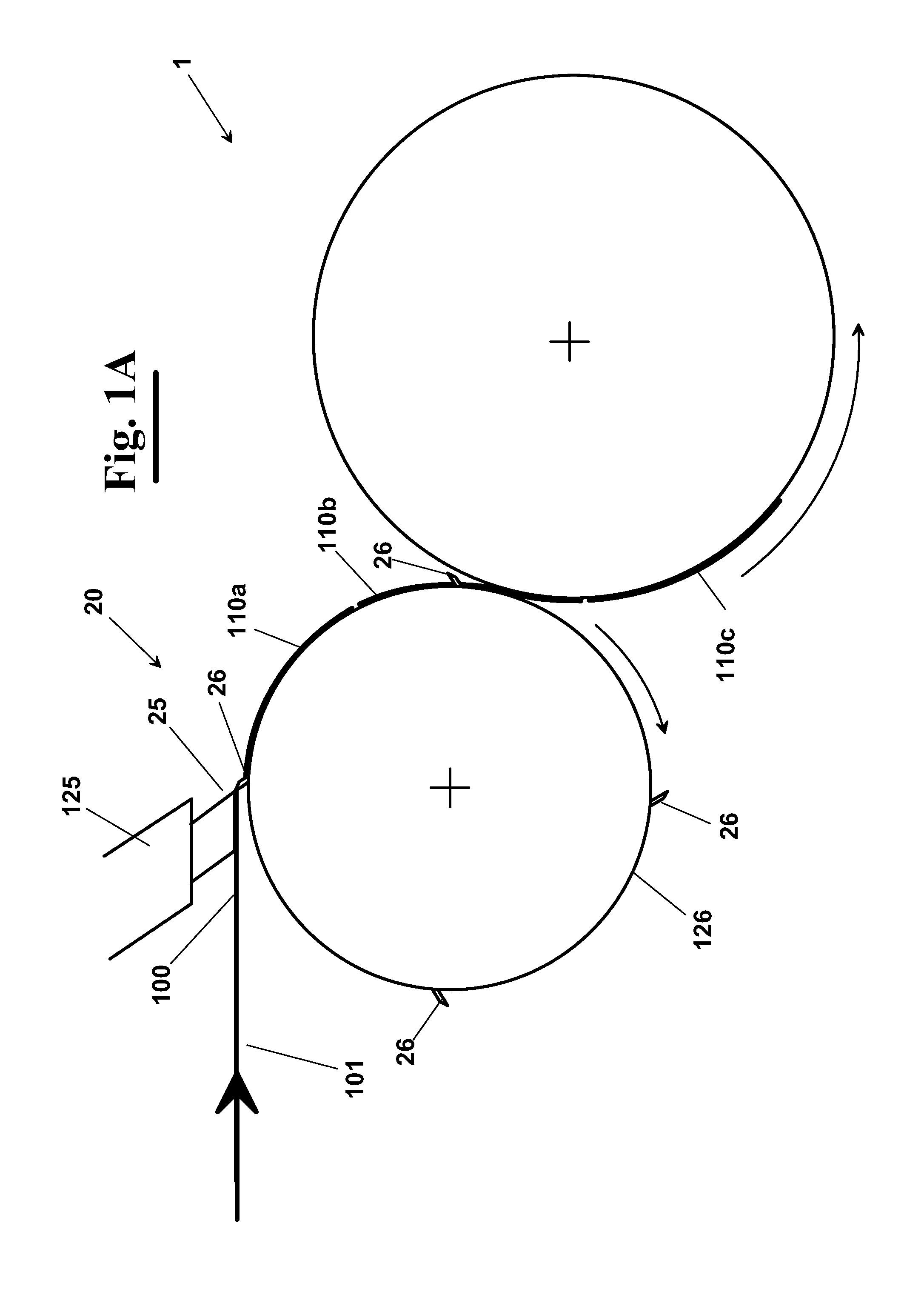
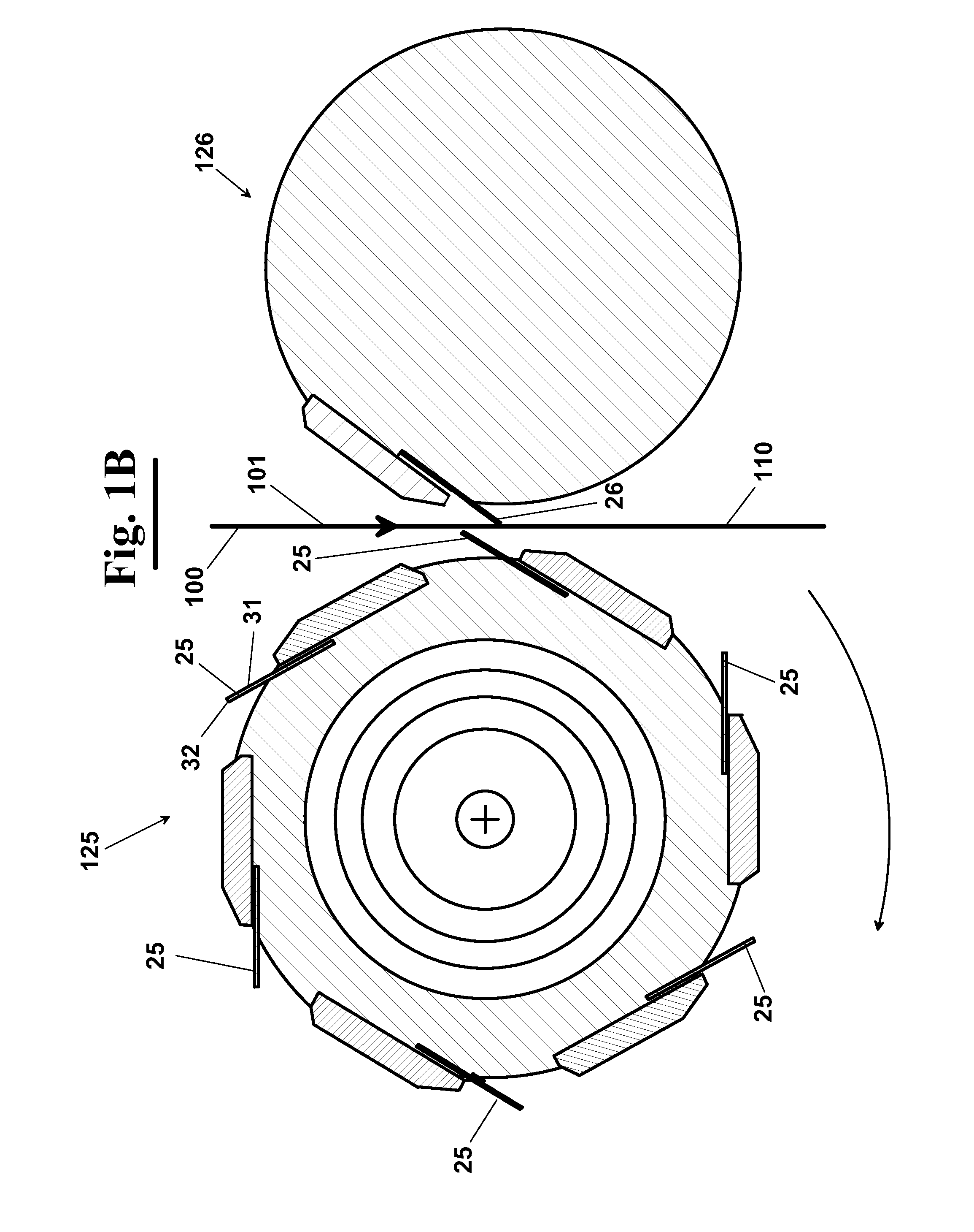
[0045]With reference to FIG. 1, a paper converting machine, according to the invention, such as a folding and stacking machine, or a rewinding machine, provides a cutting or perforation section 20, equipped with at least one blade 25, which is arranged to work in combination with a stationary knife 26 to provide the division of the web of paper 100 into a plurality of sheets 110 of measured length.

[0046]Blade 25 can be integral to a fixed support 125 (FIG. 1A), or alternatively to a cutting roller that rotates about a longitudinal rotation axis (not shown). In the case shown for example in FIG. 1B, the, or each, blade 25 can be a perforation blade, or a cutting blade, for example with helical shape, and is mounted to a perforation roller 125, whereas stationary knife 26 is mounted to a fixed roller 126. In both cases, blade 25 cuts or perforates web 100 into sheets 110, working in combination with stationary knife 26.

[0047]Blades 25 and stationary knifes 26 are as long substantially...


PUM

PropertyMeasurementUnit
Lengthaaaaaaaaaa
Structureaaaaaaaaaa
Sizeaaaaaaaaaa

Abstract

A paper converting or rewinding machine provides a cutting or perforation section, equipped with at least one blade arranged to work in combination with a stationary knife to provide the division of the web of paper into a plurality of sheets of measured length. The blade can be integral to a fixed support, or alternatively to a cutting roller that rotates about a longitudinal rotation axis. The blade(s) can be a perforation blade, or a cutting blade, with helical shape, and mounted to a perforation roller. The stationary knife can be mounted to a fixed roller. The blade performs a cutting, or perforation, of the web into sheets working in combination with the stationary knife. The blades and the stationary knifes are long substantially as the width of the paper. In particular, the blade has at least one weakened portion of determined size.

Description

FIELD OF THE INVENTION[0001]The present invention relates to the field of converting paper and similar products, and precisely it relates to folding machines, or interfolding machines, for making paper material in stacks of interfolded sheets, or to rewinding machines for making logs of web material, for example used for making rolls of toilet paper, household paper towel rolls, nonwoven fabric, jumbo rolls and the like.BACKGROUND OF THE INVENTION[0002]As well known, a variety of types exists of machines and of processes for making tissue paper products, paper towels and similar articles in stacks of folded, or interfolded sheets, such as U.S. Pat. No. 6,228,014.[0003]Furthermore, rewinding machines exist for making logs of web material for example used for making rolls of toilet paper, household paper rolls, nonwoven fabric, jumbo rolls and the like, as described in U.S. Pat. No. 6,494,398.[0004]In both types of machines, for tissue papers and for rolls, a web is subjected to a cle...

Claims


Application Information

Patent Timeline
IPC IPC(8): B26D1/22B65H35/00B31B1/14B26D1/03
CPCB26D1/0006B26D1/385B65H35/08B26D2001/002B26D2001/006B26D1/626Y10T83/2207Y10T83/0481Y10T83/647Y10T83/483Y10T83/04
Inventor DE MATTEIS, ALESSANDRO
Owner MTC MACCINE TRASFORMAZIONE CARTA SRL
Why Eureka
Eureka Blog
Learn More