Electric vehicle

a technology of electric vehicles and power units, applied in the direction of electric propulsion mounting, bicycles, transportation and packaging, etc., can solve the problems of larger transverse dimension of the housing for the housing in the vehicle, and achieve the effect of increasing the output power of the motor, reducing the dimension of the power unit in the vehicle transverse direction, and increasing the thickness of the motor

Active Publication Date: 2012-10-04
HONDA MOTOR CO LTD
View PDF8 Cites 12 Cited by
  • Summary
  • Abstract
  • Description
  • Claims
  • Application Information

AI Technical Summary

Benefits of technology

[0016]According to certain embodiments, the outer periphery of the motor and the outer periphery of the axle are close to each other, so the outside diameter of the motor can be increased to the extent that it does not interfere with the axle. Consequently, as the outside diameter of the motor is increased, the motor output power is increased, which means that the dimension of the motor in its thickness direction can be decreased and the dimension of the power unit in the vehicle transverse direction can be decreased.
[0017]According to certain embodiments, after the rotary driving power of the motor is transmitted from the gear formed at one end of the motor output shaft to the counter gear engaged with the gear and fixed on the counter shaft, it is transmitted from the gear formed at one end of the counter shaft to the output gear engaged with the gear and fixed on the differential case housing a differential mechanism, so power transmission from the motor output shaft to the axle can be achieved by a smaller number of components and a simpler constitution.
[0018]According to certain embodiments, the counter gear and the differential case overlap each other in a side view of the vehicle, so the counter shaft and the differential case can be made as close to each other as possible in order to decrease the dimension of the power unit in the vehicle longitud...

Problems solved by technology

However, the technology described in Patent Literature 1 has a problem that in the type 1 electric three-wheeled vehicle, the motor output shaft oriented along the vehicle transverse direction and the main shaft supporting a plurality of speed change gears are located on the same axis and thus the dimension of the housing for housing them in the vehicle transverse direction must be larger.
It also has a problem th...

Method used


Image

  • Electric vehicle
  • Electric vehicle
  • Electric vehicle

Examples


Embodiment Construction

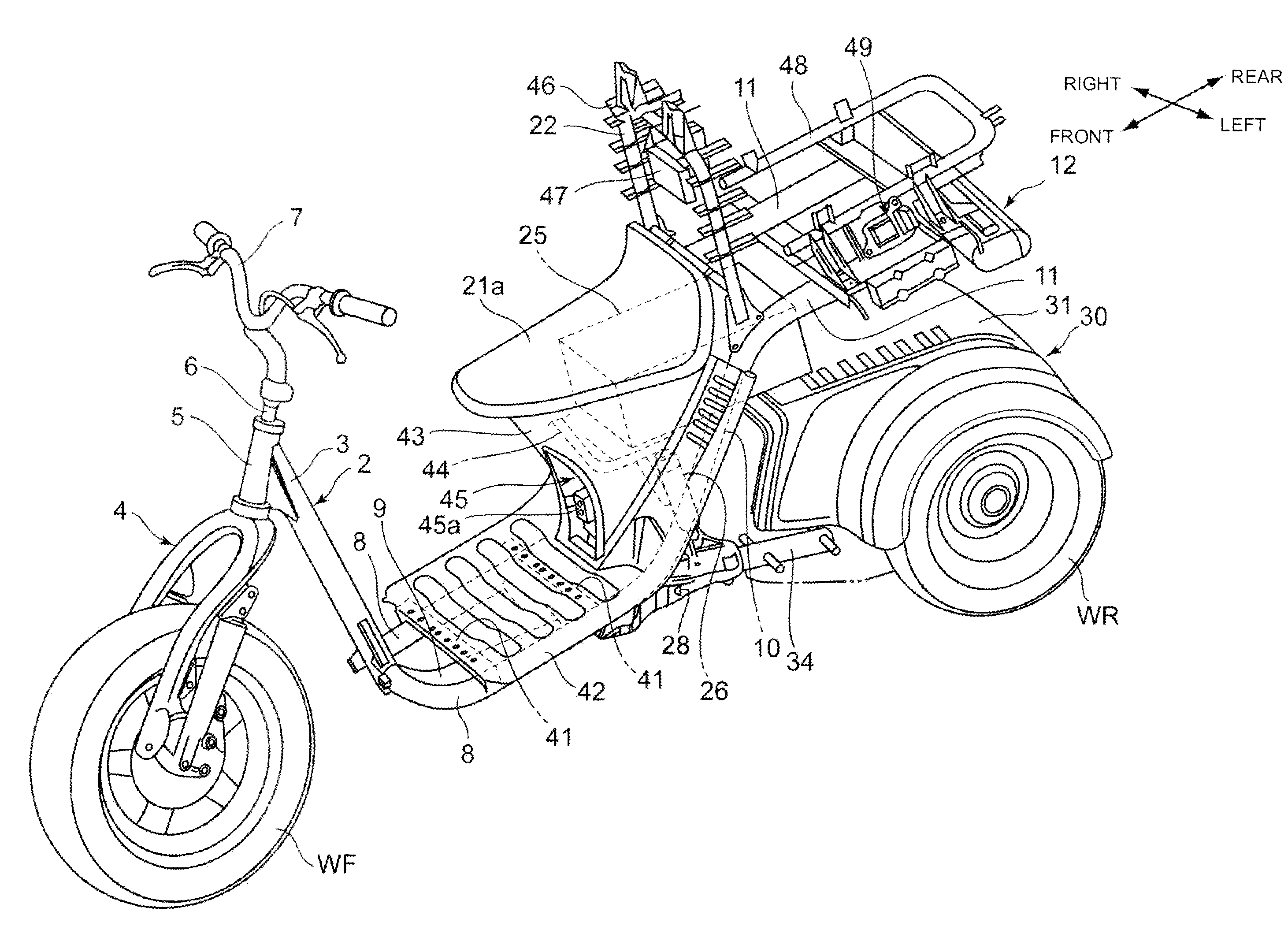
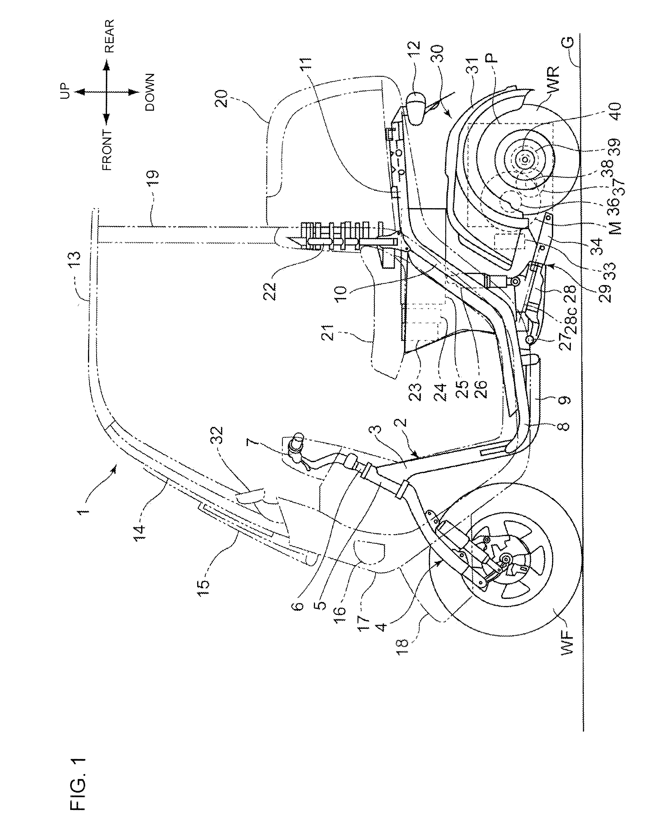
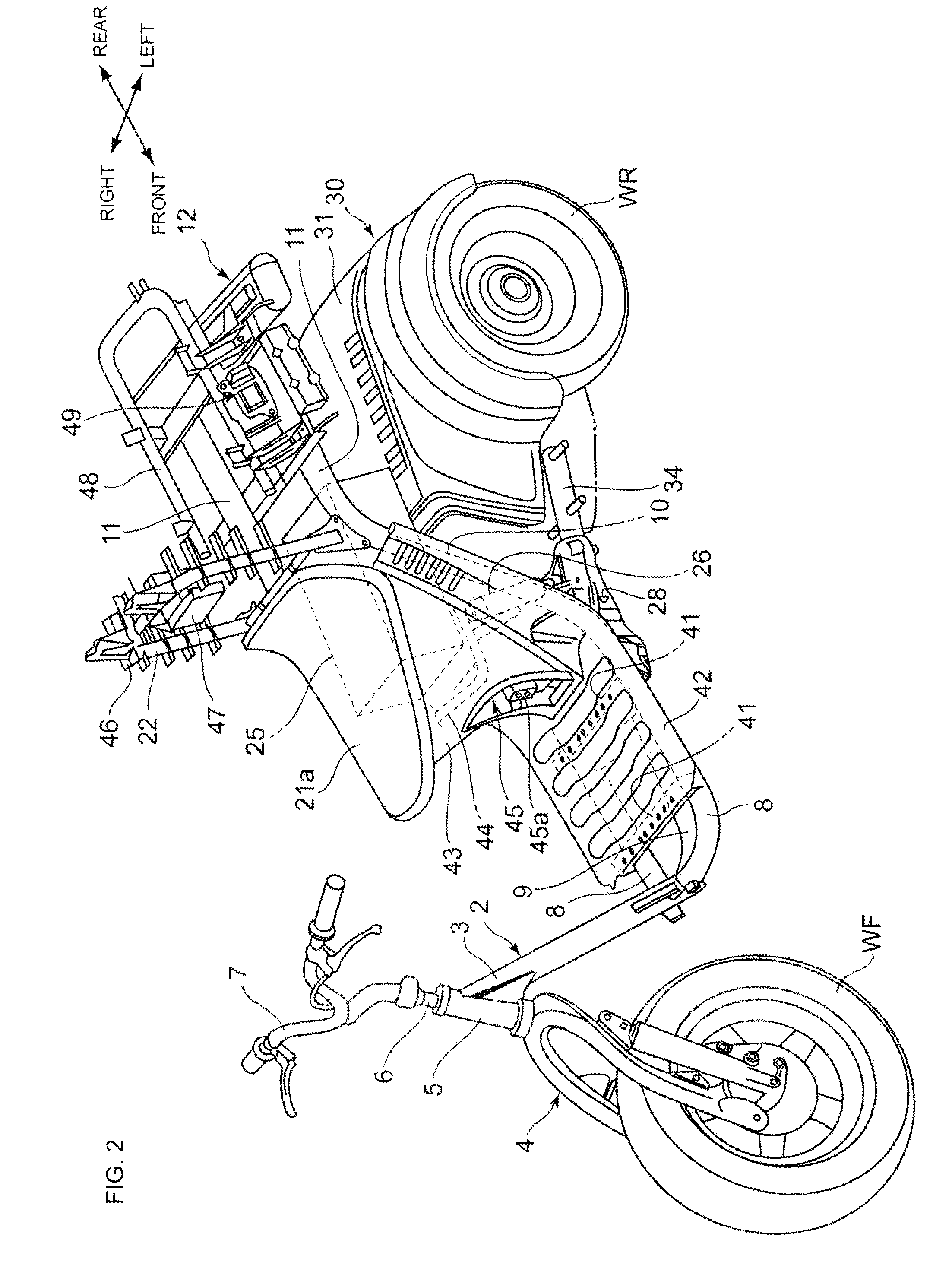
[0036]Next, the preferred embodiments of the present invention will be described in detail referring to drawings. FIG. 1 is a side view of an electric three-wheeled vehicle 1 according to an embodiment of the present invention. The electric three-wheeled vehicle 1 is a saddle-ride type vehicle which runs by driving a pair of left and right rear wheels WR by the rotary driving power of a motor M. A head pipe 5 for pivotally supporting a steering stem 6 in a rotatable manner is attached to the front end of a main frame 3 which constitutes a body frame 2. A steering handlebar 7 is attached to the top of the steering stem 6 and a bottom link type suspension (front fork) 4 for pivotally supporting a front wheel WF in a rotatable manner is attached to its bottom.

[0037]An under frame 9 in the center in the vehicle transverse direction is joined to the lower part of the main frame 3 and side frames 8 extending in the vehicle rearward direction on the left and right are also attached to it. ...


PUM


Abstract

In an electric three-wheeled vehicle, a centrifugal clutch transmits rotary driving power to a counter shaft when the revolution speed of a motor exceeds a prescribed value. The clutch is coaxially located at one end of a motor output shaft. A counter shaft is located inside the outside diameter of the motor in a side view of the vehicle. The motor output shaft, counter shaft, and axles are arranged from a vehicle forward side in the order of mention. The axis center of the counter shaft is located below a line connecting the axis center of the motor output shaft and the axis center of the axle in a side view of the vehicle.

Description

BACKGROUND[0001]1. Field[0002]The present invention relates to electric vehicles such as three-wheeled vehicles and more particularly to electric vehicles which run by driving a pair of left and right rear wheels by the driving power of a motor.[0003]2. Description of the Related Art[0004]In the past, there have been known saddle-ride type electric three-wheeled vehicles in which a front fork attached to the forward side of a body frame supports a front wheel and a rear body vertically swingable and transversely tiltable with respect to the body frame is attached on the rearward side of the body frame and a pair of left and right rear wheels driven by a motor are supported on the rear body.[0005]Patent Literature 1 (JP-A No. Hei5-161221) discloses an electric three-wheeled vehicle with a structure (type 1) in which a stepped variable transmission comprised of gear pairs attached to a main shaft and a counter shaft is provided between a motor output shaft and a rear wheel axle, and a...

Claims


Application Information

Patent Timeline
IPC IPC(8): B62D61/06B62K5/02B62K5/027B62K5/10
CPCB60K1/00B60K1/04B60K2001/001Y10S180/908B60Y2200/122F16H63/3416B60K2001/0422
Inventor MIMURA, MASAHIDENABEYA, SHINNIIZUMA, KEIICHIROSUZUKI, HITOSHI
Owner HONDA MOTOR CO LTD
Why Eureka
Try Eureka