
Quadrature Voltage Controlled Oscillator

a voltage control and oscillator technology, applied in the direction of oscillation generators, electric devices, etc., can solve the problems of image rejection, affecting system performance, increasing power consumption and sensitivity to the duty cycle of vco waveforms

Inactive Publication Date: 2012-10-04
AGENCY FOR SCI TECH & RES
View PDF11 Cites 27 Cited by
  • Summary
  • Abstract
  • Description
  • Claims
  • Application Information

AI Technical Summary

Problems solved by technology

However, the mismatch of the amplitude and phase between the in-phase and the quadrature signals degrade the image rejection and affect the system performance.
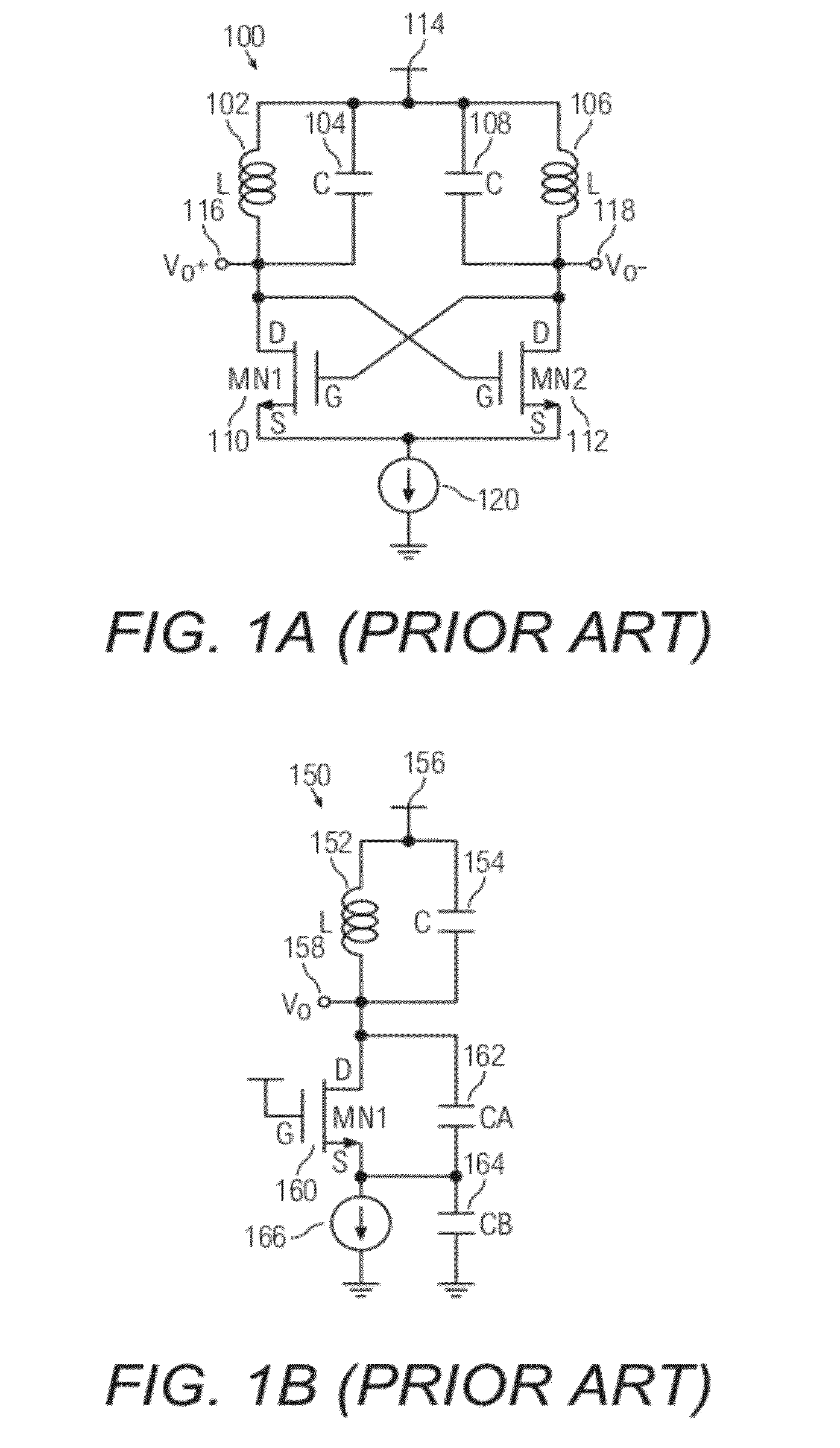
Firstly, a polyphase filter is exceptionally good at providing quadrature output from VCO but requires additional VCO output buffers for signal attenuation in the passive RC filter.
In addition, the quadrature phase accuracy is dependent on device matching and the limited operating frequency range restricts its application in implementation.
However, as the VCO operates at higher frequency, it suffers from increasing power consumption and sensitivity to the duty cycle of the VCO waveform.
However, its primary drawback is doubled die area and power consumption compared to a single VCO.
In addition, the coupled topology between the two oscillators greatly affects the phase noise, and quadrature phase accuracy, and the coupling devices or oscillators may induce too much excess phase noise.

Method used


Image

  • Quadrature Voltage Controlled Oscillator
  • Quadrature Voltage Controlled Oscillator
  • Quadrature Voltage Controlled Oscillator

Examples


Embodiment Construction

[0020]The following detailed description refers to the accompanying drawings that show, by way of illustration, specific details and embodiments in which the invention may be practiced. These embodiments are described in sufficient detail to enable those skilled in the art to practice the invention. Other embodiments may be utilized and structural, logical, and electrical changes may be made without departing from the scope of the invention. The various embodiments are not necessarily mutually exclusive, as some embodiments can be combined with one or more other embodiments to form new embodiments.

[0021]Embodiments described in the context of one of the devices are analogously valid for the other device.

[0022]In the context of various embodiments, the phrase “at least substantially” may include “exactly” and a variance of + / −5% thereof. As an example and not limitations, “A is at least substantially same as B” may encompass embodiments where A is exactly the same as B, or where A ma...


PUM


Abstract

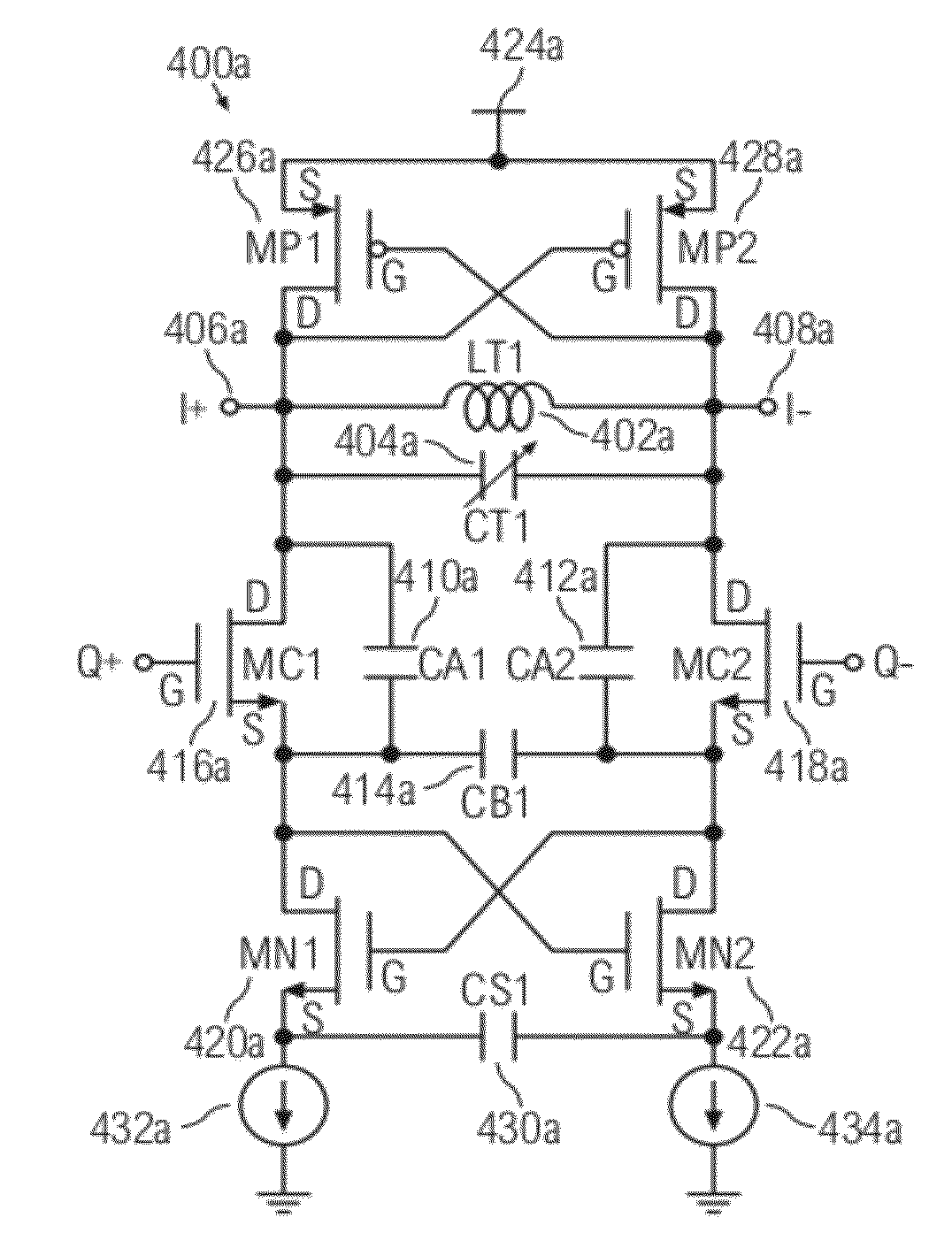
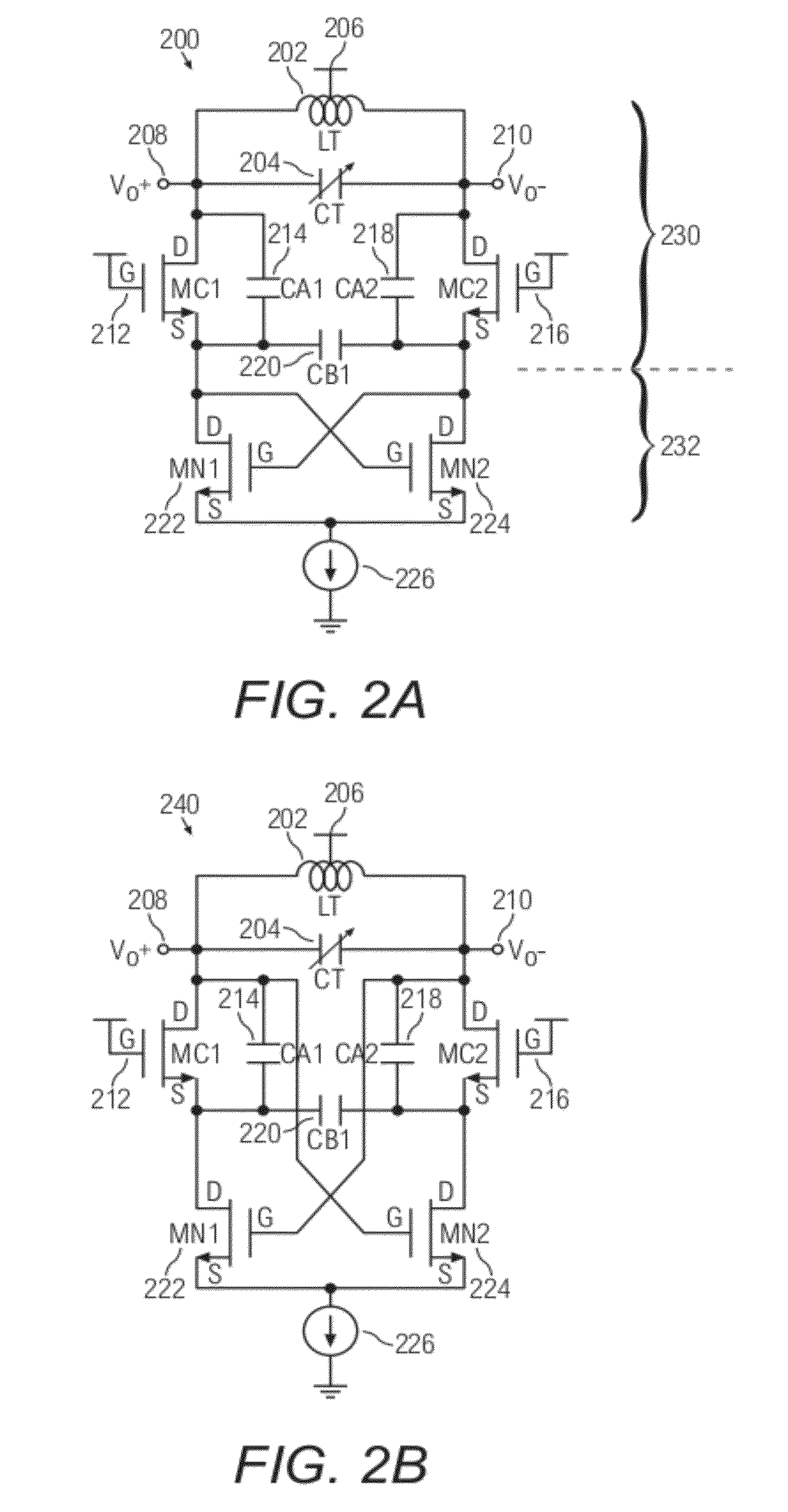
According to embodiments of the present invention, a quadrature voltage controlled oscillator is provided. The quadrature voltage controlled oscillator includes a first voltage controlled oscillator and a second voltage controlled oscillator respectively comprising an inductor having a first terminal and a second terminal, a first capacitor, a second capacitor, a third capacitor and a fourth capacitor respectively comprising a first terminal and a second terminal, a first transistor, a second transistor, a third transistor and a fourth transistor respectively comprising a source terminal, a drain terminal and a gate terminal, wherein the first terminal of the inductor is coupled to the first terminal of the first capacitor, and the second terminal of the inductor is coupled to the second terminal of the first capacitor, wherein the drain terminal of the first transistor is coupled to the first terminal of the inductor, the first terminal of the first capacitor, the first terminal of the second capacitor, and the gate terminal of the fourth transistor, wherein the drain terminal of the second transistor is coupled to the second terminal of the inductor, the second terminal of the first capacitor, the first terminal of the third capacitor, and the gate terminal of the third transistor, wherein the source terminal of the first transistor is coupled to the second terminal of the second capacitor, the drain terminal of the third transistor, and the first terminal of the fourth capacitor, wherein the source terminal of the second transistor is coupled to the second terminal of the third capacitor, the drain terminal of the fourth transistor, and the second terminal of the fourth capacitor, wherein the gate terminal of the first transistor of the first voltage controlled oscillator is directly coupled to the first terminal of the inductor of the second voltage controlled oscillator, wherein the gate terminal of the second transistor of the first voltage controlled oscillator is directly coupled to the second terminal of the inductor of the second voltage controlled oscillator, wherein the gate terminal of the first transistor of the second voltage controlled oscillator is directly coupled to the second terminal of the inductor of the first voltage controlled oscillator, wherein the gate terminal of the second transistor of the second voltage controlled oscillator is directly coupled to the first terminal of the inductor of the first voltage controlled oscillator.

Description

[0001]This application claims the benefit of priority of Singapore patent application No. 201102304-1, filed 31 Mar. 2011, the content of it being hereby incorporated by reference in its entirety for all purposes.FIELD OF THE INVENTIONS[0002]Various embodiments relate to a quadrature voltage controlled oscillator (QVCO).BACKGROUND OF THE INVENTIONS[0003]A quadrature receiver front-end is an essential component for integrated communication systems. It contains two mixers in an in-phase receiving path and in a quadrature receiving path, respectively, converting the received signal into a low intermediate frequency (IF). In each receiving path, the mixers are delivered by an in-phase signal and a quadrature signal, respectively. A key building block for such I / Q modulation (demodulation) is the voltage-controlled oscillator (VCO) with quadrature outputs, e.g. the quadrature VCO (QVCO). However, the mismatch of the amplitude and phase between the in-phase and the quadrature signals degr...

Claims


Application Information

Patent Timeline
Patent Type & Authority Applications(United States)
IPC IPC(8): H03B27/00
CPCH03B27/00H03B5/1243H03B5/1212H03B5/1228
Inventor CHENG, KUANG-WEIJE, MINKYU
Owner AGENCY FOR SCI TECH & RES
Learn More