
Apparatus to Control Carrier Spacing in a Multi-Carrier Optical Transmitter

Active Publication Date: 2012-10-04
INFINERA CORP
View PDF7 Cites 16 Cited by
  • Summary
  • Abstract
  • Description
  • Claims
  • Application Information

AI Technical Summary

Benefits of technology

[0008]Consistent with one aspect of the present disclosure, an apparatus includes a first optical source configured to supply a first optical signal having a first frequency and a second optical source configured to supply a second optical signal having a second frequency, the first and second optical signals being provided as ones of a plurality of optical signals. Also included is

Problems solved by technology

At 50 GHz channel spacing and 100 GHz channel spacing, the occupied optical fiber bandwidth or spectrum is not efficiently used.
Such higher rate modulation formats, however, are typically more susceptible to noise, and, therefore, may not be used in transmission of optical signals over relatively long distances.
However, conforming to such a restrictive frequency grid, while convenient, may undesirably limit the data carrying capacity of an optical communication system.
Unless the wavelength of each optical signal is controlled, the wavelengths of the optical signals may drift and could equal one another, such that the optical signals interfere with one another.
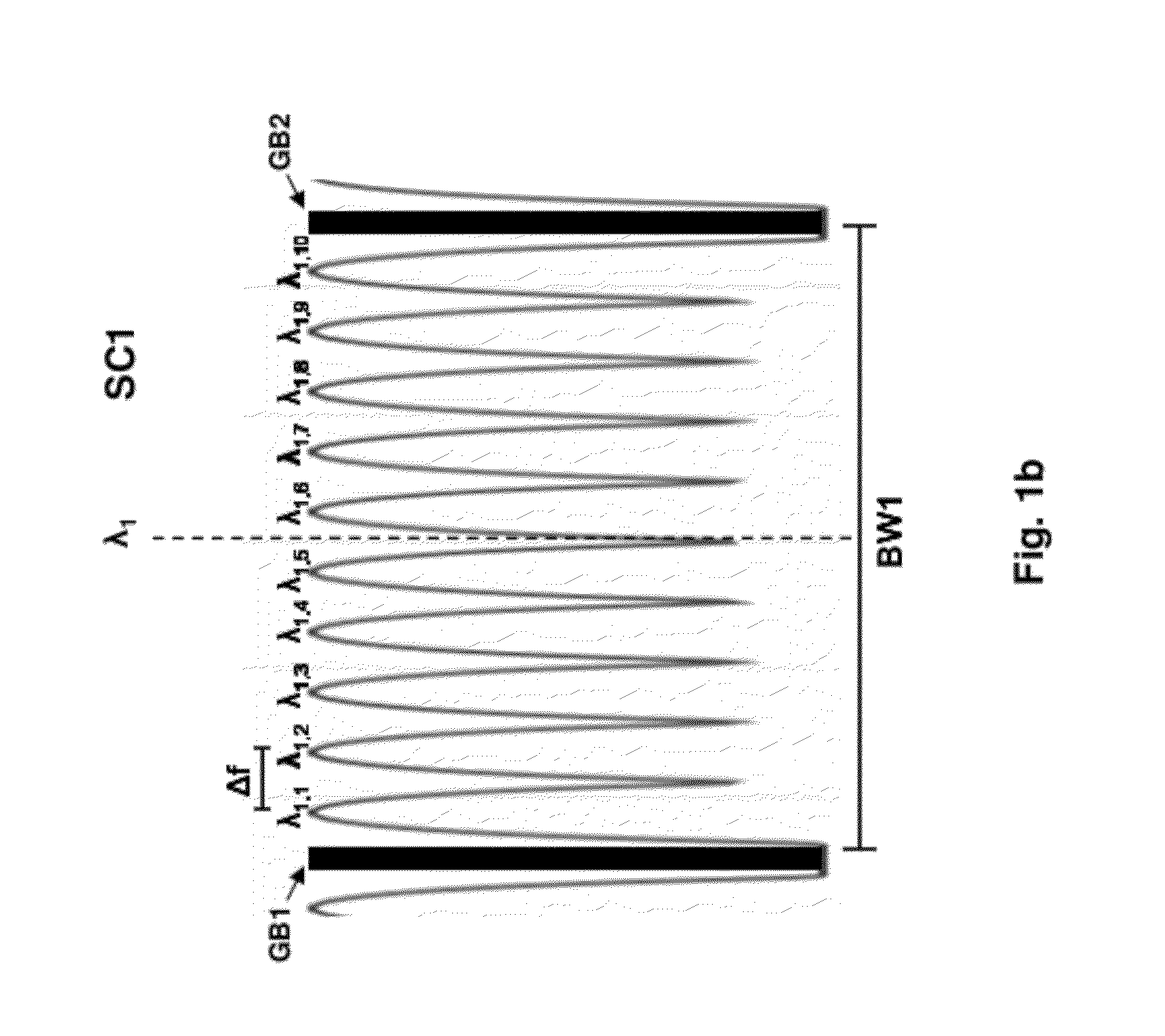
Wavelength control may be particularly difficult when the wavelengths are tightly or minimally spaced, such as when the optical signals collectively constitute a “superchannel.”
FP etalons have been developed with a FSR of 50 GHz or less, but to realize such an FP etalon, the physical thickness of the optical component is typically too large to be satisfactorily implemented.
Additionally, FP etalons exhibit frequency errors.
However, if the carrier frequency spacing or carrier spacing is small, the frequency errors are a significant fraction of the carrier spacing.

Method used


Image

  • Apparatus to Control Carrier Spacing in a Multi-Carrier Optical Transmitter
  • Apparatus to Control Carrier Spacing in a Multi-Carrier Optical Transmitter
  • Apparatus to Control Carrier Spacing in a Multi-Carrier Optical Transmitter

Examples


Embodiment Construction

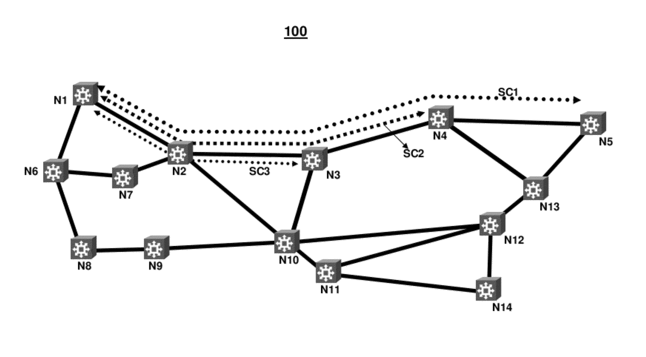
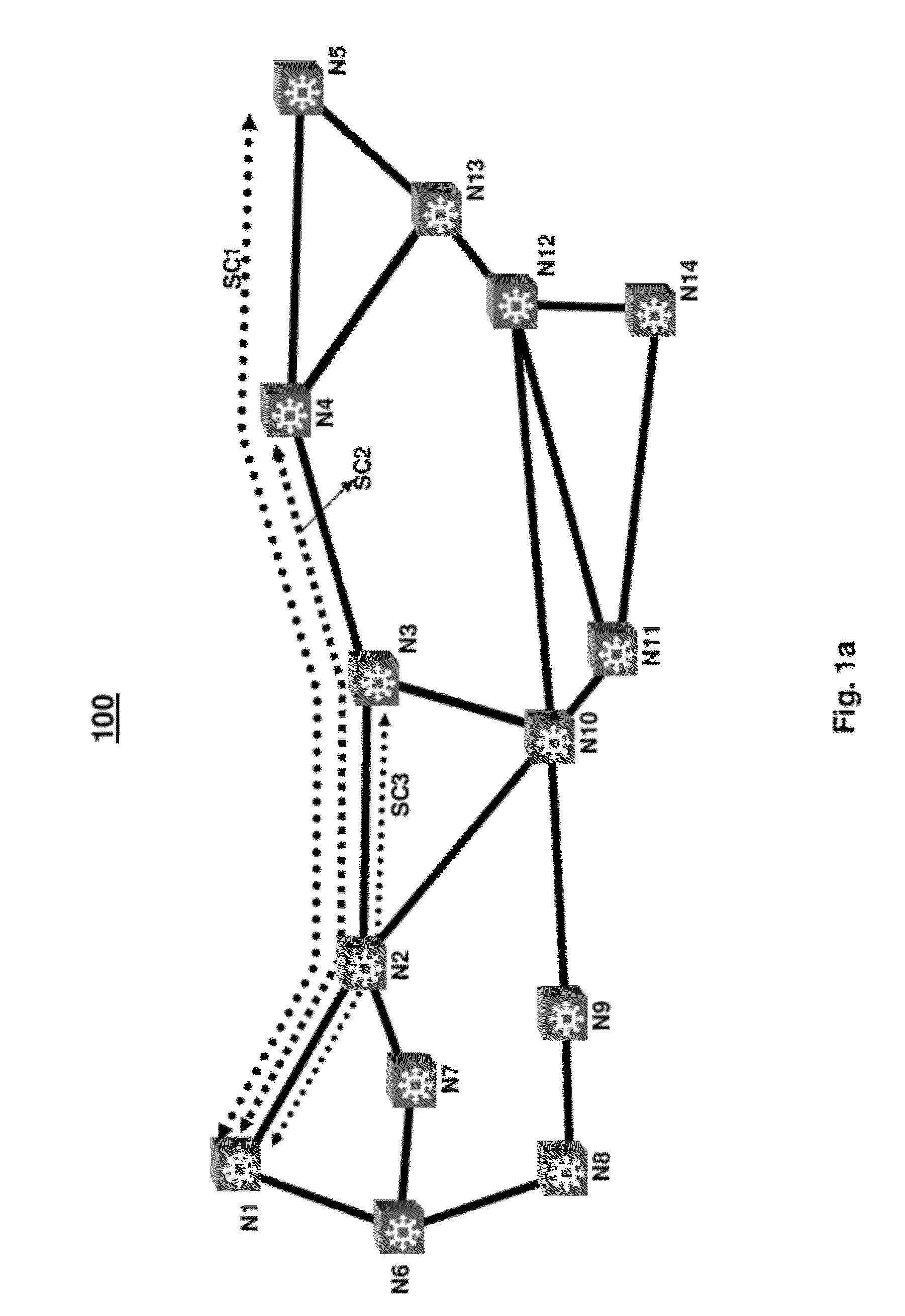
[0025]Consistent with the present disclosure, data, in digital form, is received by a transmit node of an optical communication system. In response to the received data, a modulator modulates light output from a laser to provide a modulated optical signal. Typically, a plurality of such modulators and lasers are provided, and each of the corresponding modulated optical signals or carriers has a respective one of a plurality of wavelengths. The wavelengths are spectrally spaced from one another in a uniform manner, and may thus be considered periodic. Preferably, the optical signals have wavelengths that are minimally spaced from one another, such that the optical signals collectively constitute a superchannel. In one example, a plurality of superchannels may be transmitted in an optical communication system.

[0026]In order to control the wavelength or frequency of each optical signal in the superchannel, optical signal frequencies or wavelengths may be locked or controlled relative t...


PUM


Abstract

Consistent with the present disclosure, data, in digital form, is received by a transmit node of an optical communication system, and is then provided to a modulator that, in turn, modulates light, received from an optical source at one of a plurality of periodically and preferably minimally spaced wavelengths. The plurality of periodically spaced wavelengths or carriers are grouped together with minimal carrier spacing, to form a superchannel. The carrier spacing between adjacent carriers is determined by detecting a beat frequency of a combined optical signal that includes the outputs of two adjacent optical sources. The beat frequency corresponds to a frequency difference between the outputs of the adjacent carriers. This frequency difference should correspond to a desired carrier spacing between each of the plurality of carriers. A frequency error between the beat frequency and the desired carrier spacing is then measured by down-converting the beat frequency with respect to a target reference frequency corresponding to the desired carrier frequency spacing. Based on the determined frequency error, the optical sources are controlled to adjust in frequency to minimize or reduce the frequency error to zero. For every pair of adjacent carriers, the corresponding outputs of the optical sources are compared in the above manner to determine a plurality of frequency errors. Each optical source can thus be tuned in order to realize a precise carrier spacing between each of the adjacent carriers.

Description

BACKGROUND OF THE DISCLOSURE[0001]Wavelength division multiplexed (WDM) optical communication systems are known in which multiple optical signals or channels, each having a different wavelength, are combined onto an optical fiber. Such systems typically include a laser associated with each wavelength, a modulator configured to modulate the optical signal output from the laser, and an optical combiner to combine each of the modulated optical signals. Such components are typically provided at a transmit end of the WDM optical communication system to transmit the optical signals onto the optical fiber. At a receive end of the WDM optical communication system, the optical signals are often separated and converted to corresponding electrical signals that are then processed further.[0002]Known WDM optical communication systems are capable of multiplexing 40 channels at 100 GHz spacing or 80 channels at 50 GHz spacing. These WDM optical communication systems occupy an overall bandwidth of ...

Claims


Application Information

Patent Timeline
IPC IPC(8): H04B10/08
CPCH04J14/02H04B10/506H04B10/572
Inventor MCNICOL, JOHN D.VAN LEEUWEN, MICHAEL FRANCISMERTZ, PIERREXU, HAI
Owner INFINERA CORP
Learn More