Supercharge Your Innovation With Domain-Expert AI Agents!

Multiple rotor fluid transfer engine

a fluid transfer engine and multi-rotor technology, applied in the direction of machines/engines, liquid fuel engines, mechanical equipment, etc., can solve the problems of inconvenient maintenance, inconvenient maintenance, and inability to provide desired efficiencies of current reciprocating engines, etc., to achieve the effect of reducing maintenance costs, reducing maintenance costs, and increasing maintenance costs

Inactive Publication Date: 2012-10-04
GYROTON CORP
View PDF12 Cites 2 Cited by
  • Summary
  • Abstract
  • Description
  • Claims
  • Application Information

AI Technical Summary

Benefits of technology

The engine achieves high efficiency with mechanical reliability and lower costs by optimizing displacement volumes and minimizing fluid momentum interruptions through precise sealing and geometric design, enabling effective thermodynamic conversions and fluid handling.

Problems solved by technology

Current reciprocating engines, rod pumps and vane devices do not provide desired efficiencies.
Further, these devices tend to be mechanically complex and thus costly and difficult to maintain.

Method used


Image

  • Multiple rotor fluid transfer engine
  • Multiple rotor fluid transfer engine
  • Multiple rotor fluid transfer engine

Examples


Embodiment Construction

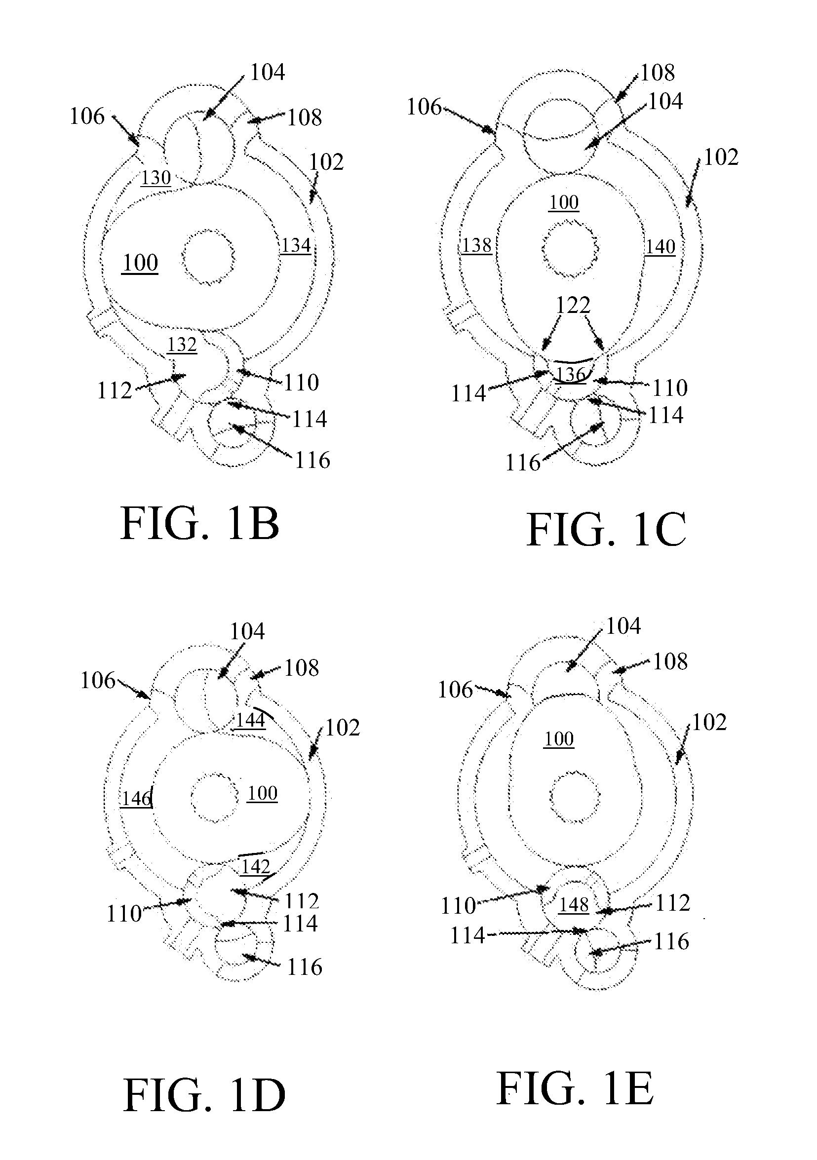
[0035]An embodiment of the present invention employed as an internal combustion engine shown in FIG. 1A consists of a cylindrical housing 102 in which an oblong main rotor 100 spins. A clearance rotor 104 is located between an intake port 106 and an exhaust port 108 and rotates partially within the main cylinder so as to engage and form seals with the main rotor 100. A compression rotor 110 is also located to spin partially within the main cylinder so as to engage and form seals with the main rotor. The compression rotor also serves substantially as the combustion chamber for the cycle. The cylinder 112 in which the compression rotor spins is fit with an exhaust port 114, through which spent gases may be purged by un-fueled air. A purge rotor 116 is connected to this compression rotor exhaust port, enabling the port to be cyclically opened and closed. The four rotors 100, 104, 110, 116 are geared, external to the cylindrical housing via drive shafts on each rotor such that they spin...


PUM


Abstract

A fluid transfer engine employs a case with a cylindrical inner wall having an operating radius extending from a case axis. A main rotor is carried within the case and incorporates a lobe with a major radius equal to and concentric with the operating radius of the case, the main rotor having a minor radius defining a body. Two peripheral rotors are diametrically opposed with respect to the case axis and rotate within rotor chambers extending from the case. Each peripheral rotor has a radius equal to the minor radius and a center of rotation located at twice the minor radius from the case axis. Each of the peripheral rotors rotates in uniform circular motion with the main rotor in sealing contact with the body and incorporates a sculpted recess for receiving the lobe of the main rotor.

Description

REFERENCE TO RELATED APPLICATIONS[0001]This application is a divisional of application Ser. No. 12 / 391,070 filed on Feb. 23, 2009 entitled Multiple Rotor Fluid Transfer Engine which is a continuation in part of application Ser. No. 11 / 189,137 filed on Jul. 25, 2005 entitled Asymmetric Complete Expansion Rotary Engine Cycle now issued as U.S. Pat. No. 7,493,885 on Feb. 24, 2009 which is in turn a continuation of application Ser. No. 09 / 570,323 having a filing date of May 12, 2000 entitled Asymmetric Complete Expansion Rotary Engine Cycle, issued as U.S. Pat. No. 6,955,153 on Oct. 18, 2005, all having a common assignee with the present application, the disclosures of which are both incorporated herein by reference.BACKGROUND[0002]1. Field[0003]This invention relates to engines for fluid transfer including hydraulic pumps / motors and gas compressor / expanders, and more particularly to multiple rotor engines employing uniform circular motion of multiple interacting rotors.[0004]2. Descrip...

Claims


Application Information

Patent Timeline
Patent Type & Authority Applications(United States)
IPC IPC(8): F01C1/12F04C2/12
CPCF01C1/20F02B53/00Y02T10/17F02B57/00F02B2730/015F02B55/02Y02T10/12
Inventor PEITZKE, WILLIAM R.BROWN, MATTHEWDEHLSEN, JAMES G.P.GRIECO, CHRISTOPHER J.
Owner GYROTON CORP
Features
  • R&D
  • Intellectual Property
  • Life Sciences
  • Materials
  • Tech Scout
  • Unparalleled Data Quality
  • Higher Quality Content
  • 60% Fewer Hallucinations
Learn More