Method and program for calculating correction value for machine tool

a technology of correction value and machine tool, which is applied in the direction of electric programme control, program control, instruments, etc., can solve the problems of difficult to completely eliminate geometric errors, deterioration of machine tool accuracy, and difficulty in machining the object to be machined, so as to reduce the life of the tool, improve the appearance quality, and improve the accuracy of the machine tool.

Active Publication Date: 2012-10-04
OKUMA CORP
View PDF12 Cites 8 Cited by
  • Summary
  • Abstract
  • Description
  • Claims
  • Application Information

AI Technical Summary

Benefits of technology

[0013]According to the present invention, while the correction value for each of the translational axes is changed in the case where each of the rotational axes operates, the correction value for each of the translational axes is not changed in the case where it operates. Therefore, even in the case where each of the rotational axes is indexed to carry out flattening, drilling, or the like, a decrease in the accuracy of a machined surface, a deterioration in appearance quality, or a reduction in the life span of the tool is not caused. As a result, machining is carried out with high accuracy.

Problems solved by technology

The presence of a geometric error leads to a deterioration in the accuracy in the motion of the machine tool, and to a deterioration in the accuracy in the machining of the object to be machined.
Therefore, the geometric error needs to be reduced through adjustment, but it is difficult to completely eliminate the geometric error.
Such an operation may adversely affect the accuracy in machining such as flattening, drilling, or the like.
Further, in the case where a rectilinear axis is guided through sliding, when this rectilinear axis is operated in an infinitesimal manner as described above, the axis moves sometimes, and does not move at other times. That is, so-called “stop feed” occurs to bring about a deterioration in the properties of a machined surface, such as the creation of irregularities along the machined surface or the like.
Therefore, an abnormality in the diameter of a bore occurs, and also a reduction in the life span of the drill are incurred.

Method used


Image

  • Method and program for calculating correction value for machine tool
  • Method and program for calculating correction value for machine tool
  • Method and program for calculating correction value for machine tool

Examples


first embodiment

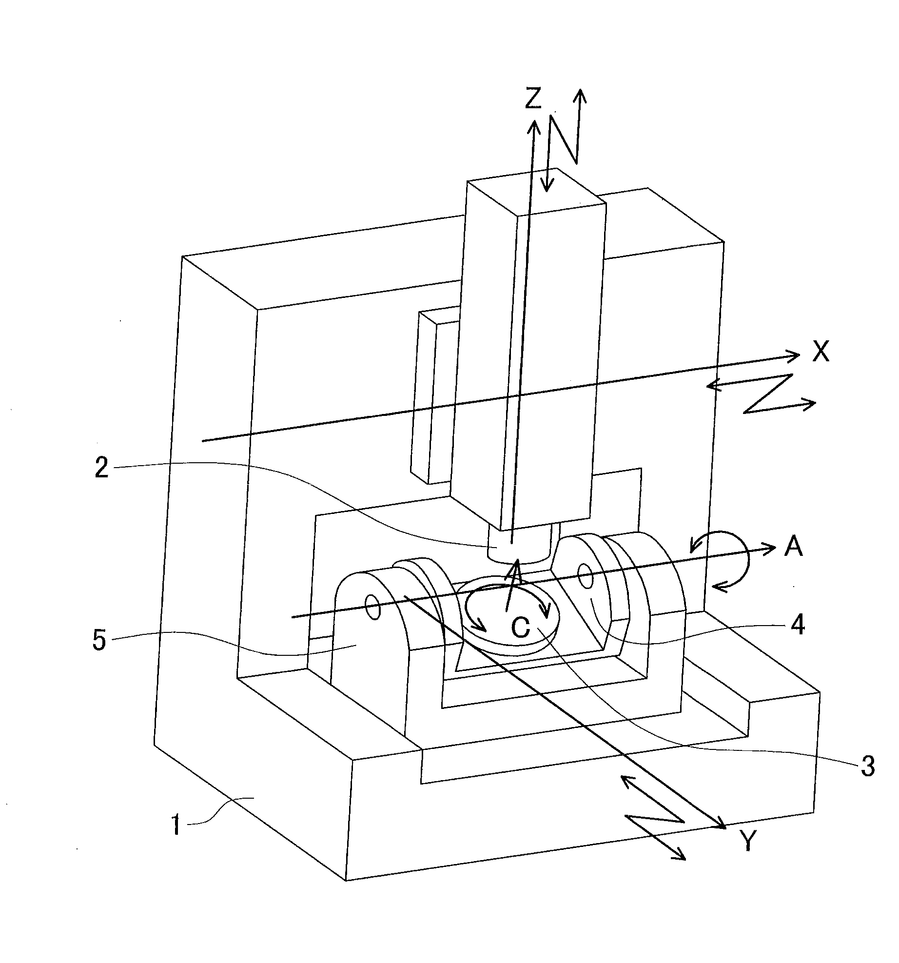
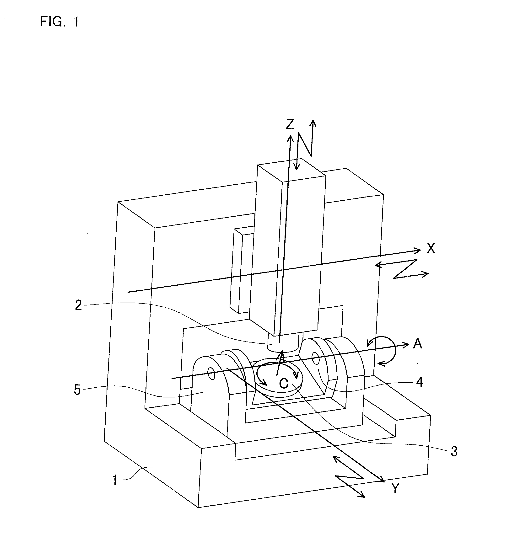
[0021]A correction made in the five-axis machine shown in FIG. 1 will be described hereinafter as an example of an embodiment according to the present invention, on the basis of the drawings as needed. This correction is made by a computer that executes a correction program. The computer may be a numerical control device for the five-axis machine, an independent control device connected to the numerical control device, or a combination of these control devices. It should be noted that this embodiment of the present invention is not limited to an example shown below. For example, it may also be applied to a machine tool having four or less axes or six or more axes, that the rotational axes may provide the spindle head 2 with two degrees of freedom of rotation instead of providing the table 3 with two degrees of freedom of rotation, or that the rotational axes may provide each of the spindle head 2 and the table 3 with one or more degrees of freedom of rotation. Further, instead of th...

second embodiment

[0035]Subsequently, the second embodiment of the present invention will be described, focusing on what is different from the first embodiment of the present invention. The second embodiment of the present invention is identical in physical configuration to the first embodiment of the present invention, but is different therefrom in the method of calculating a correction value.

[0036]That is, in calculation according to the second embodiment of the present invention, a correction reference point is defined not as a point on a command value coordinate system, but as a point on an arbitrary table reference coordinate system. The table reference coordinate system is a coordinate system fixed on the table 3. This coordinate system moves as the table 3 is rotated or inclined on the command value coordinate system. FIG. 5 is an example of the table reference coordinate system and the correction reference point. An origin Ow of the table reference coordinate system, with which the apex of th...


PUM

PropertyMeasurementUnit
degrees of freedomaaaaaaaaaa
degree of freedomaaaaaaaaaa

Abstract

The present invention provides a method and the like that are capable of calculating a correction value for a rotational axis and make it possible to correct an error in position or position and posture of a tool, which results from a geometric error, correct an error in posture of the tool, and also enhance the accuracy in machining by preventing a translational axis from operating in an infinitesimal manner due to a correction command. In a machine tool having two or more translational axes and one or more rotational axes, a correction value for each of the translational axes is calculated using a command position of each of the rotational axes, a coordinate value of a correction reference point as one point designated in advance in a command position space of each of the translational axes, and a geometric parameter representing the geometrical error.

Description

BACKGROUND OF INVENTION[0001]This application claims the benefit of Japanese Patent Application Number 2011-083080 filed on Apr. 4, 2011, the entirety of which is incorporated by reference.TECHNICAL FIELD[0002]The present invention relates to a method and a program for calculating a correction value for correcting a geometric error in a machine tool having translational axes and rotational axes.BACKGROUND ART[0003]FIG. 1 is a schematic view of a machine tool (a five-axis control machining center or a five-axis machine) having three translational axes and two rotational axes, as an example of the above-described machine tool. A spindle head 2 can make motions with two degrees of freedom of translation with respect to a bed 1, along X- and Z-axes as translational axes, which are perpendicular to each other. A table 3 can make motions with one degree of freedom of rotation with respect to a cradle 4, around a C-axis as a rotational axis. The cradle 4 can make motions with one degree of...

Claims


Application Information

Patent Timeline
Patent Type & Authority Applications(United States)
IPC IPC(8): G05B19/19
CPCG05B2219/50285Y10T409/305824G05B19/404B23Q1/5406B23Q1/4857
Inventor MATSUSHITA, TETSUYA
Owner OKUMA CORP
Why Eureka
Try Eureka