Aircraft landing gear automated inspection for presence of internal oxygen contamination

a technology for landing gear and aircraft, which is applied in the direction of special data processing applications, electric/magnetic measuring arrangements, and vehicle registration/indication, etc., and can solve the problems of shortening the anticipated fatigue life of components, difficult to sell or re-lease the returned, and affecting the quality of the returned

Active Publication Date: 2012-10-04
NANCE C KIRK
View PDF13 Cites 12 Cited by
  • Summary
  • Abstract
  • Description
  • Claims
  • Application Information

AI Technical Summary

Problems solved by technology

The aircraft manufacturer must consider the possibility that bad weather at the airport or poor landing skills of less experienced pilots might cause “hard landing events”, which put much greater strain on the components and drastically shorten the anticipated fatigue life of the components.
Aircraft manufacturers which offer their airplanes through lease arrangements often find that after the initial lease period, it difficult to sell or re-lease the returned, mid-life aircraft, when the aircraft are returned with an expensive component such as the landing gear system, “run-out” to the absolute limits of its useful life.
Many of these airports sometimes have limited resources for maintaining the aircraft.
This is the point where oxygen can possibly be introduced to the inside of the landing gear, thus create an environment which will promote internal corrosion.
Thus the environment which can promote corrosion can compound.
These maintenance mis-practices are well known within the airline industry as well as by the aircraft manufacturers, but the manufacturers have no way to correct the problem for introduction of oxygen to the landing gear struts .
. . thus the manufacturers will often assume a worst-case scenario, when they publish the Calendar Life limitations for the landing gear overhaul cycles.
There are two primary limitations which aircraft landing gear manufactures place upon their equipment, in an attempt to insure the landing gear strut remains in a robust configuration.
These two limitations are “Number of Landing Cycles” and “Calendar Life” limitation.
Internal corrosion, which degrades landing gear structural integrity, is primarily caused by the introduction of oxygen to the inside the landing gear strut.
The dissipation of these landing loads generates a large amount of internal heat within the landing gear strut.
The compression of the strut increases internal strut pressure and thus increases heat within the strut chamber, while the flammable fluid is distributed within the oxygen contamination of the strut; thus a diesel explosion can occur.

Method used


Image

  • Aircraft landing gear automated inspection for presence of internal oxygen contamination
  • Aircraft landing gear automated inspection for presence of internal oxygen contamination
  • Aircraft landing gear automated inspection for presence of internal oxygen contamination

Examples


Embodiment Construction

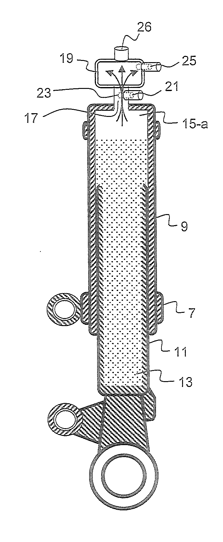
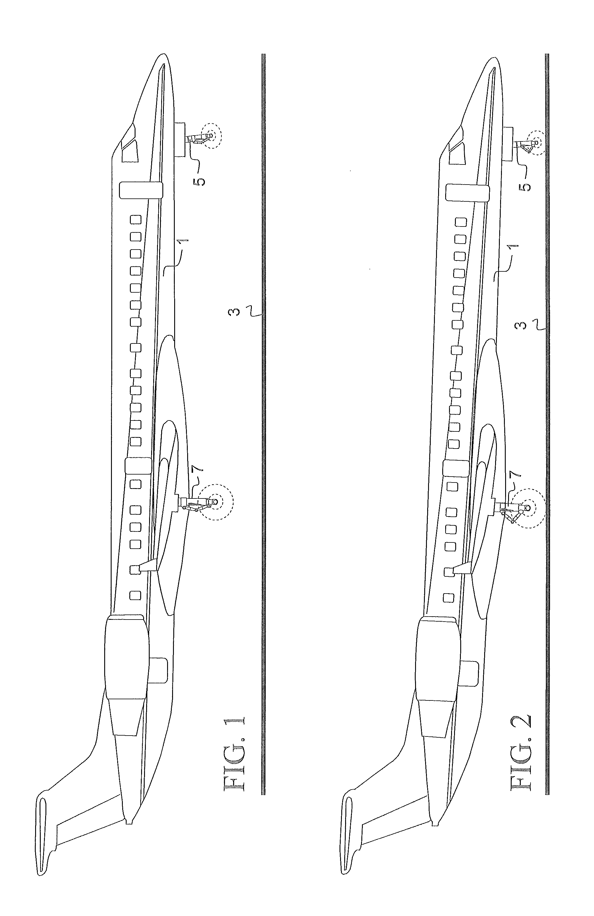
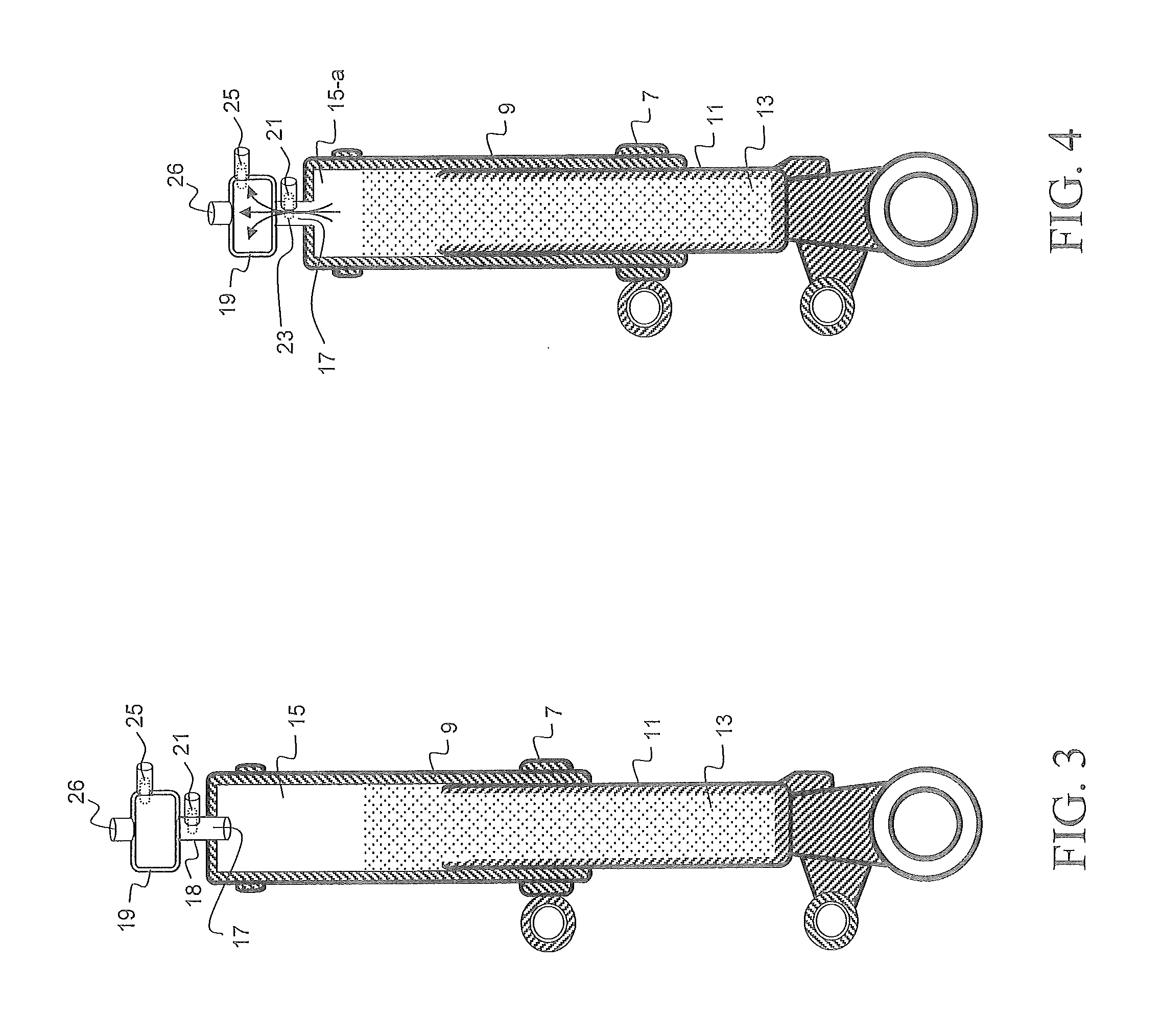
[0028]An aircraft is typically supported by plural pressurized landing gear struts. Each landing gear strut is designed much like, and incorporates many of the features of a typical shock absorber. The shock absorber of the landing gear strut comprises internal fluids, both hydraulic fluid and compressed nitrogen gas. Nitrogen, being an inert gas, will not promote corrosion to the internal components or combustion within the landing gear. Still, landing gear manufacturers realize improper landing gear servicing practices exist, throughout the world. Landing gear struts which appear to be low, and when access to a bottle of compressed nitrogen gas is not available, the landing gear are often injected with compressed air, or even sometimes compressed O2 (which is typically located at most aircraft maintenance facilities, for use to re-charge the pilot / cockpit emergency oxygen tanks, onboard the aircraft). The introduction of oxygen into the landing gear strut creates an internal envir...


PUM


Abstract

A system for use in monitoring, measuring, recording, computing and transmitting the oxygen levels and identification of oxygen contamination within an aircraft telescopic landing gear strut. An oxygen sensor is mounted in relation to each of the landing gear struts as to monitor, recognize, measure and record the identification of oxygen within the telescopic landing gear struts. The amount of oxygen within each landing gear strut is measured and recorded and downloaded to the responsible aircraft maintenance department. By detecting the amount of oxygen in a strut, steps can be taken to purge the gas from the strut to minimize corrosion of strut components and to prevent internal combustion of the gas and oil in the strut.

Description

[0001]This application claims the benefit of U.S. provisional patent application Ser. No. 61 / 470,528, filed Apr. 1, 2011.BACKGROUND OF THE INVENTION[0002]There are many critical factors the pilot of an aircraft must consider with an aircraft before departure. One of those factors is the correct servicing levels of the internal fluids within the aircraft landing gear struts. Aircraft manufacturers determine, certify and publish maximum gross take-off and landing weight limitations of the aircraft. Aircraft manufacturers also have restrictions regarding the maximum allowable weight the aircraft landing gear and other supporting structures can safely absorb, when the aircraft lands. These landing weight restrictions are often determined not by how much weight the landing gear can safely handle at any single landing, but more as to the fatigue life of the landing gear system, in relation to the life expectancy of the aircraft, as a whole. The aircraft manufacturer must consider the poss...

Claims


Application Information

Patent Timeline
Patent Type & Authority Applications(United States)
IPC IPC(8): B64F5/00G01M17/00
CPCB64C25/60G01M17/04B64F5/0045B64F5/60
Inventor NANCE, C. KIRK
Owner NANCE C KIRK
Why Eureka
Try Eureka