Accessing local network resources in a multi-interface system

a multi-interface system and accessing local network resources technology, applied in the direction of connection management, instruments, digital computers, etc., can solve the problem of preventing the client device from accessing network resources

Active Publication Date: 2012-10-04
WILMERDING COMM LLC
View PDF2 Cites 29 Cited by
  • Summary
  • Abstract
  • Description
  • Claims
  • Application Information

AI Technical Summary

Benefits of technology

[0005]The present invention allows applications on clients running multi-interface software or hardware, or unmodified client devices located behind a client router running multi-interface software or hard

Problems solved by technology

Unfortunately, this process prevents the client device from accessing network resources that are only accessible vi

Method used


Image

  • Accessing local network resources in a multi-interface system
  • Accessing local network resources in a multi-interface system
  • Accessing local network resources in a multi-interface system

Examples


second embodiment

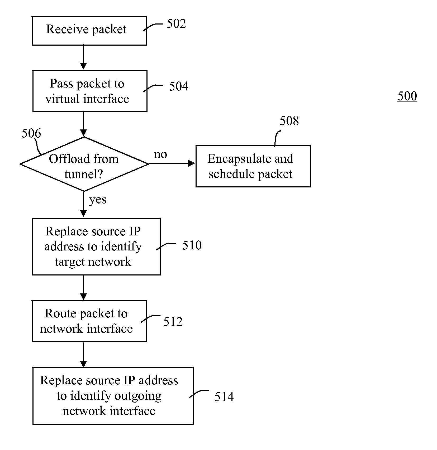
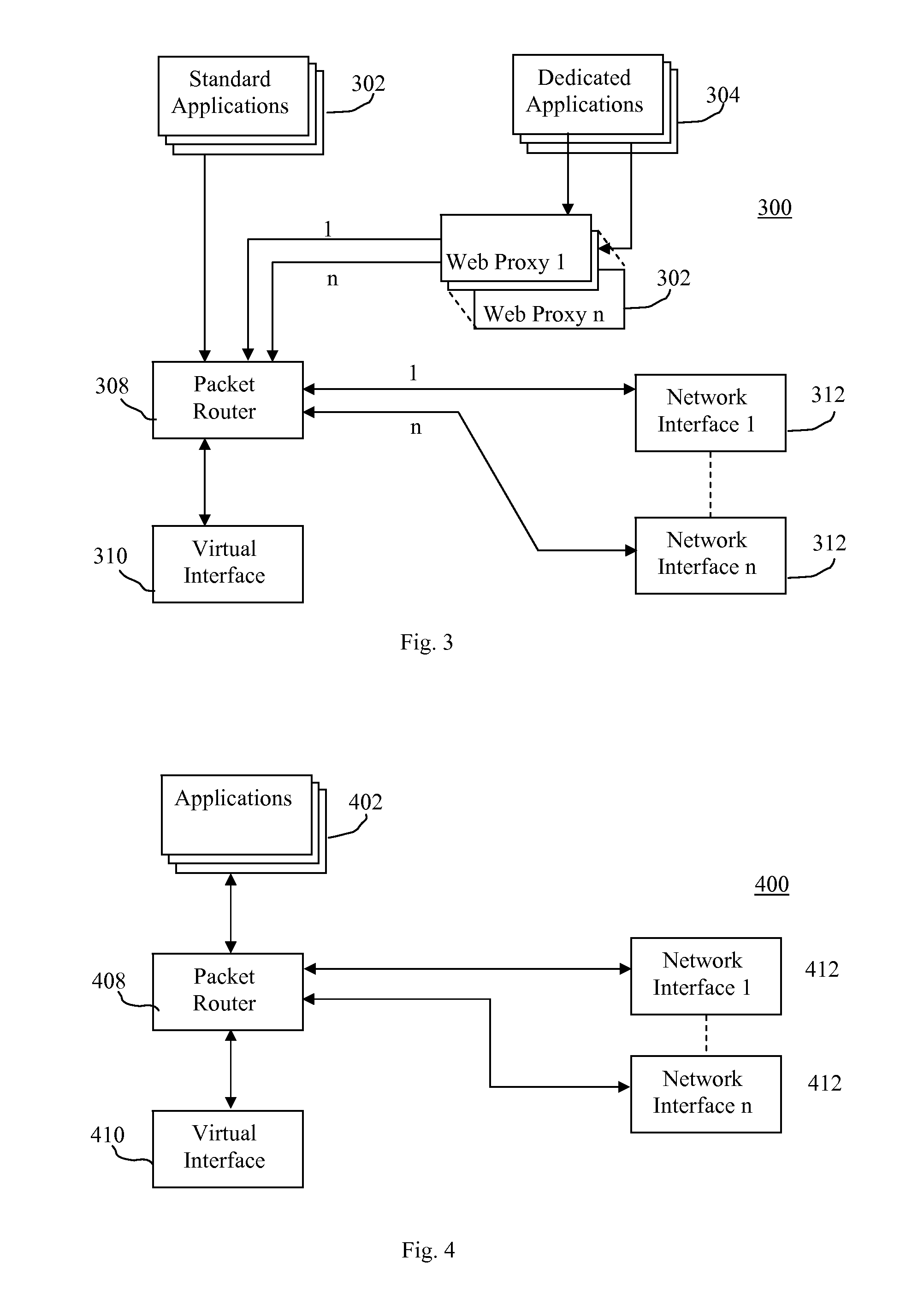
[0033]Referring to FIG. 4, software modules executing on the client device 102 in accordance with the invention are illustrated generally by numeral 400. The software modules include applications 402, a packet router 408, a virtual interface 410, and a plurality of network interfaces 412. Unlike the previous embodiment, the present embodiment does not use web proxies 306 to offload traffic from the tunnel. Rather, in the present embodiment, the virtual interface is configured to rewrite the packet source address, thereby affecting the packet routing, as will be described below.

[0034]The virtual interface 410 is configured with a static, private Internet protocol (IP) address, such as 192.168.1.1 / 24 for example. The IP address assigned to the virtual interface is different from the IP addresses on all other network interfaces. In the present embodiment, the IP address for the Wi-Fi interface is 1.1.1.1 / 24 and the IP address for the 3G interface is 22.2.2 / 24.

[0035]The virtual interfac...

third embodiment

[0049]However, some operating systems may not be able to readily replace source and destination IP address as described above. Accordingly, in a third embodiment, IP header-fields other than the IP address can be used to manipulate routing decisions. For example, the Linux kernel enables packet routing based not only upon the IP address, but also on other fields such as the Terms of Service (ToS) fields in an IP packet. By mapping different values to the ToS fields, it is possible to route packets in a similar manner as discussed above with regard to IP address replacement. Thus, client devices 102 that do not support source address routing may be similarly configured, but using a different IP header field that is supported. This can be extended to include classifying packets based on any field in the packet, using Layer 7 inspection. Prepending a custom header, which is ignored by the network interface 412, would make it possible to route the packet based on any field in the packet...

fourth embodiment

[0051]In a fourth embodiment, the virtual interface 410 is set as a default interface for the client device 102. Accordingly, the virtual interface 410 captures all of the traffic generated from or destined for the applications 402 and acts as a transparent protocol proxy. When a connection is made from a client application 402 to a destination server 110, the virtual interface 410 will see the connection request message. Instead of forwarding this connection request on, the virtual interface 410 will respond to the client application 402 as if it were the destination server 110. Concurrently, the virtual interface 410 will establish a connection to the destinations server 110 over one of the specific network interfaces. This connection request will be properly routed because the connection from virtual interface 410 will originate from the source of the network interface 412 which this connection has been determined to be assigned to. This assignment is performed in the same manner...


PUM


Abstract

A method is provided for selectively routing data packets on a client device having of plurality of network interfaces for communicating over a network. The method comprising the following steps. It is determined if the data packets should be routed to a network server accessible by a corresponding one of the network interfaces to access local resources offered thereon. If the data packets should be routed to the network server, the data packets are routed directly to the network server via the corresponding network interface. Otherwise, the data packets are routed via a default route. A client device configured to implement the method is also provided.

Description

[0001]The present invention relates generally to multi-interface communication systems and specifically to accessing network resources that are not available over a default network interface when implementing such systems.BACKGROUND[0002]Multi-interface communication systems allow client devices to use multiple network interfaces as if they were a single network interface. This is achieved by providing a network component that acts as an agent for the client device. The client device can be configured to use any number of network interfaces at the same time, as well as move traffic between interfaces.[0003]Examples of multi-interface communication systems are provided in U.S. patent application Ser. No. 13 / 004,652, titled “Communication Between Client and Server Using Multiple Networks” by Manku et al. (hereafter referred to as “Manku”) and U.S. Pat. No. 7,539,175, titled “Multi-Access Terminal with Capability for Simultaneous Connectivity to Multiple Communication Channels” by Whit...

Claims


Application Information

Patent Timeline
IPC IPC(8): G06F15/173H04L45/24H04L47/43
CPCH04L45/24H04L45/00H04W76/022H04W76/12H04L69/329H04L65/00
Inventor ARMSTRONG, NICHOLASSCHMIDTKE, JAKUBROBINSON, ROBERTTSUI, SEVERN
Owner WILMERDING COMM LLC
Why Eureka
Try Eureka