High power laser pipeline tool and methods of use

a laser and pipeline technology, applied in the direction of manufacturing tools, branching pipes, instruments, etc., can solve the problems of pipeline accidents and failures, damage and abatement, corrosion and damag, and cost the pipeline industry more than $5 billion annually, and achieve the effect of high power laser energy

Active Publication Date: 2012-10-11
FORO ENERGY
View PDF8 Cites 75 Cited by
  • Summary
  • Abstract
  • Description
  • Claims
  • Application Information

AI Technical Summary

Benefits of technology

[0025]Still further there is provided a method of treating the interior of a pipeline having: positioning a high power laser outside of the pipeline for providing high power laser energy; positioning a laser-pig adjacent to the pipeline and in optical communication with the high power laser; moving the laser-pig into the pipeline; while maintaining the laser-pig in optical communication with the high power laser; and, delivering the high power laser energy from the laser-pig to the interior of the pipeline.
[0026]Additionally, there are provided the forgoing embodiments which may further be such that the tool, method or system may employ or utilize the following: a high power laser cable having a length of greater than about 1 mile and having a high power optical fiber having a core having a diameter of greater than about 300 μm; a second high power laser tool, wherein the first or second high power laser tool is selected from at least one of a laser cutter, a laser illuminator, and a laser monitor; a laser source having a power of at least about 15 kW and a wavelength in the range of from about 800 nm to about 1600 nm; and, a mobile system.
[0027]Still, additionally, there are provided the forgoing embodiments which may further be such that the tool, method or system may employ or utilize the following: the laser pig having a high power laser tool; the launching section having a valve in fluid communication with the holder section; the feed through section having a packer; and, the optical capable section having a high power optical cable having a length of greater than about 1 mile, a means for winding and unwinding the optical cable, and a high power optical fiber having a core having a diameter of at least about 200 μm; a laser source having a power of at least about 10 kW; the launching section having a valve in fluid communication with the holder section; the feed through section having a means for managing pressure between the launching section and the optical cable section; and, the optical capable section having a high power optical cable having a length of greater than about 1 mile and a high power optical fiber having a core having a diameter of at least about 500 μm.
[0028]Yet, additionally, there are provided the forgoing embodiments which may further be such that the tool, method or system may employ or utilize the following: a laser source having a power of at least about 5 kW,...

Problems solved by technology

Pipeline Corrosion and Damage
Pipeline accidents and failures can be caused by many sources, including for example: external damage from excavators and nature; material deficiencies; stress cracking; weld, grout or joint deficiencies; corrosion; and combinations of these and other events.
Corrosion has been related to several recent natural gas transmission pipelines a...

Method used


Image

  • High power laser pipeline tool and methods of use
  • High power laser pipeline tool and methods of use
  • High power laser pipeline tool and methods of use

Examples


Embodiment Construction

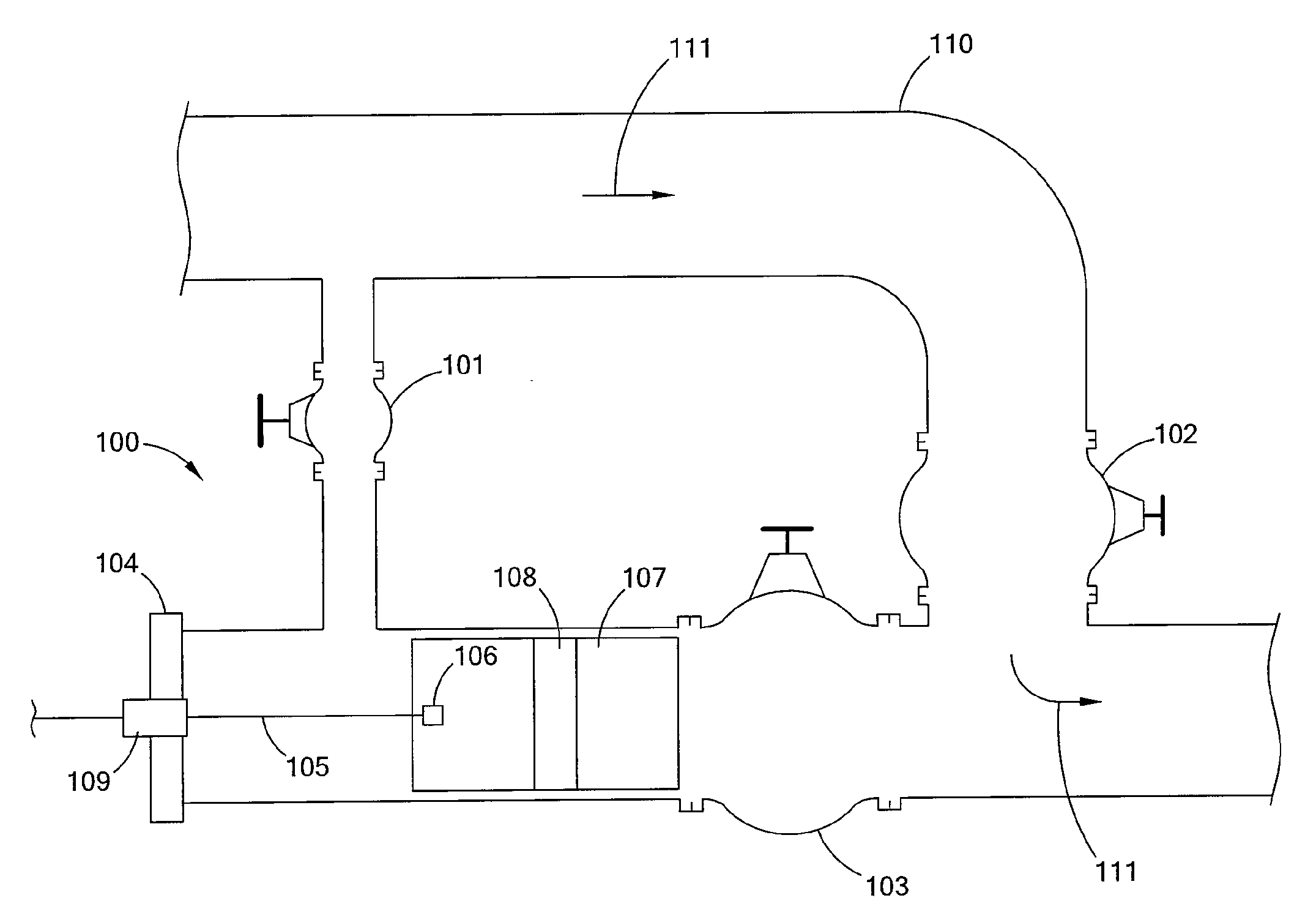
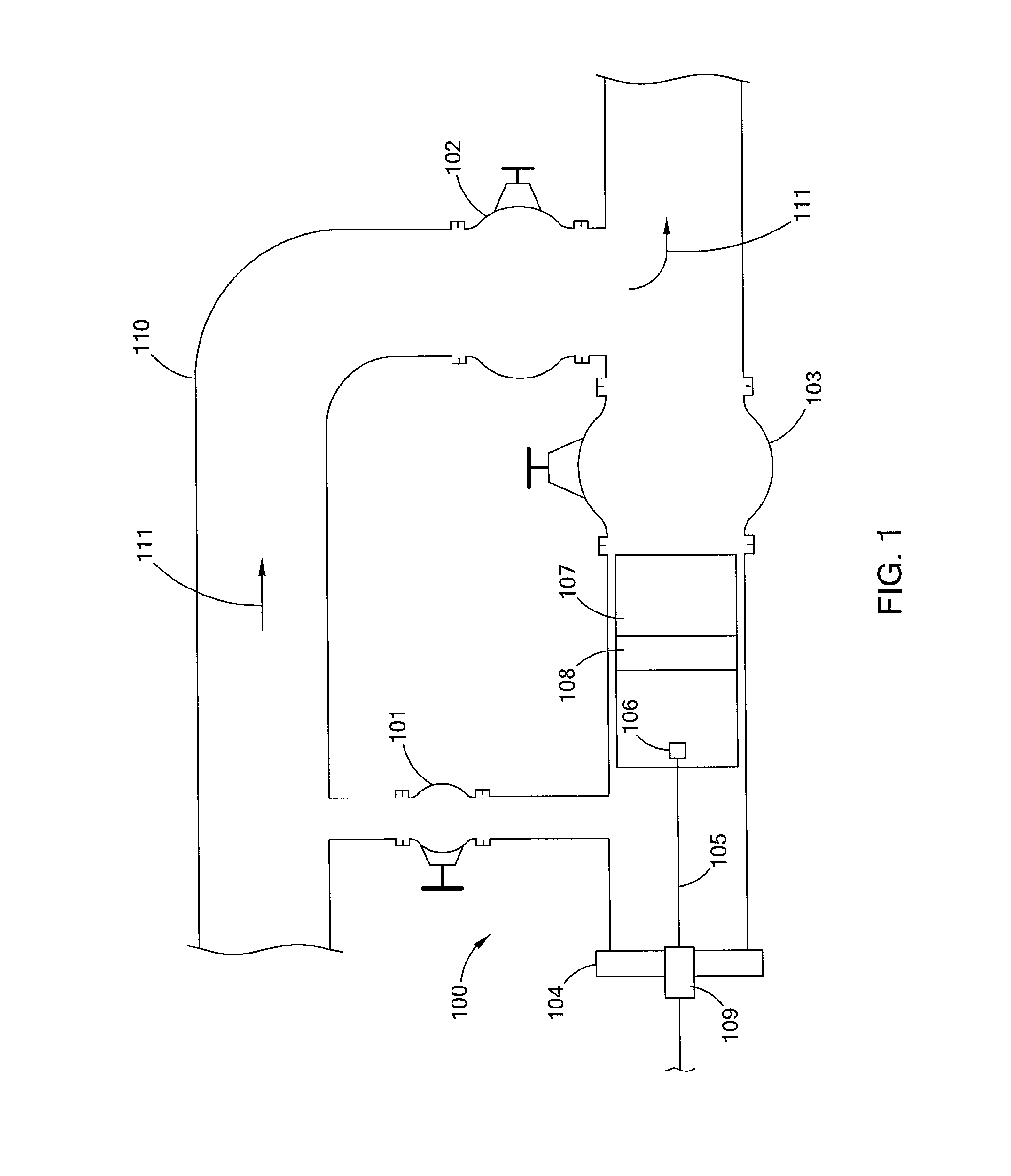
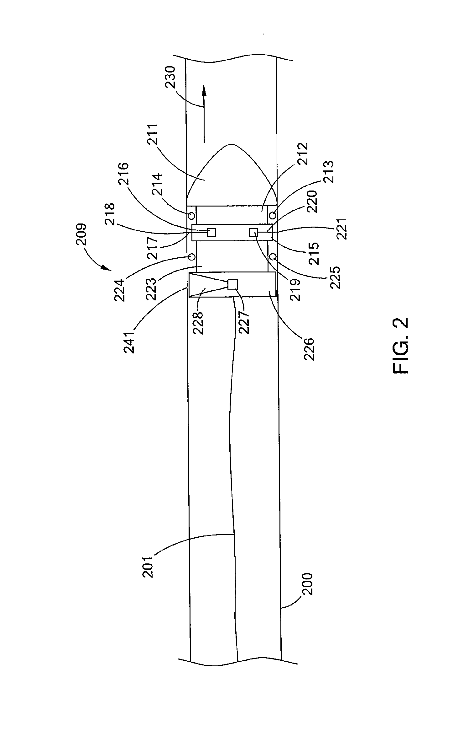
[0038]In general, the present inventions relate to high power laser pipeline tools that can be used for pipeline activities, such as for example inspecting, cleaning, measuring, analyzing, maintaining, welding, assembling, or other activities known to the pipeline arts, or that may be recognized in the future based upon the present inventions and teachings of this specification. By way of general illustration there is provided a pipeline tool that has as a laser tool for performing pipeline activities, e.g., a laser-pig. The laser-pig utilizes a high power laser tool, which is in optical communication, by way of a high power optical fiber cable, with a high power laser that is located outside of the pipeline. The laser-pig may also have cups or other structures, which use the movement of the fluid through the pipeline as a motive means for the laser-pig. The laser-pig may also have braking devices, or similar devices as part of the cups or otherwise, that regulate and / or control t...


PUM

PropertyMeasurementUnit
Lengthaaaaaaaaaa
Lengthaaaaaaaaaa
Lengthaaaaaaaaaa

Abstract

There is provided a high power laser tool system for transmitting and delivering high power laser energy within the interior of pipes, which includes a high power laser-pig and long distance high power optical tether. The high power laser system performs high power laser pigging operations and other operations, such as, cleaning, assembling, maintaining and monitoring of pipelines.

Description

[0001]This application: (i) claims, under 35 U.S.C. §119(e)(1), the benefit of the filing date of Feb. 7, 2011 of U.S. provisional application Ser. No. 61 / 439,970; (ii) claims, under 35 U.S.C. §119(e)(1), the benefit of the filing date of Feb. 24, 2011 of U.S. provisional application Ser. No. 61 / 446,312; (iii) is a continuation-in-part of U.S. patent application Ser. No. 12 / 706,576 filed Feb. 16, 2010, which is a continuation-in-part of U.S. patent application Ser. No. 12 / 544,136 filed Aug. 19, 2009, and which claims under 35 U.S.C. §119(e)(1) the benefit of the filing date of Feb. 17, 2009 of U.S. provisional application Ser. No. 61 / 153,271, and the benefit of the filing date of Jan. 15, 2010 of U.S. provisional application Ser. No. 61 / 295,562; (iv) is a continuation-in-part of U.S. patent application Ser. No. 12 / 840,978 filed Jul. 21, 2010; (v) is a continuation-in-part of U.S. patent application Ser. No. 12 / 543,986 filed Aug. 19, 2009; (vi) is a continuation-in-part of U.S. paten...

Claims


Application Information

Patent Timeline
IPC IPC(8): B23K26/00
CPCG02B6/502B08B9/055B08B7/0042B08B9/02F16L55/46F16L41/004
Inventor MCKAY, RYAN P.RINZLER, CHARLES C.MOXLEY, JOEL F.DEUTCH, PAUL D.ZEDIKER, MARK S.DEWITT, RONALD A.FAIRCLOTH, BRIAN O.
Owner FORO ENERGY
Why Eureka
Try Eureka