Corrugated Solder Pre-form and Method of Use

Inactive Publication Date: 2012-10-11
ANDREW LLC
View PDF2 Cites 8 Cited by
  • Summary
  • Abstract
  • Description
  • Claims
  • Application Information

AI Technical Summary

Problems solved by technology

Aluminum material exposed to air quickly oxidizes, forming an aluminum oxide coating that interferes w

Method used


Image

  • Corrugated Solder Pre-form and Method of Use
  • Corrugated Solder Pre-form and Method of Use
  • Corrugated Solder Pre-form and Method of Use

Examples


Embodiment Construction

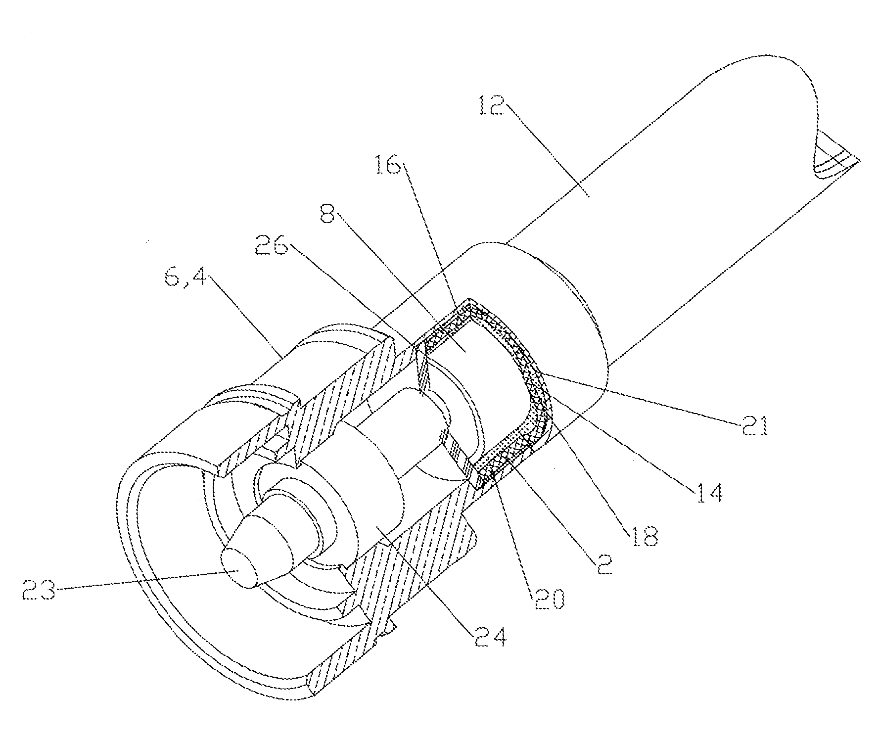
[0027]The inventor has recognized that significant difficulties arise when attempting to solder a coaxial connector to a smooth sidewall outer conductor coaxial cable when the connector body and / or coaxial cable outer conductor are aluminum material.

[0028]The inventor's analysis indicates that, due to the speed of the aluminum oxide coating formation, if the aluminum material surfaces to be soldered are not coated with the flux immediately prior to initiation of heating to melt the solder pre-form, the quality of the resulting solder interconnection may be degraded. When the flux is heated as soldering is initiated, the flux volatizes, wetting and acid washing away the aluminum oxide coating likely present on the aluminum material surfaces, immediately prior to the melting of the solder pre-form to solder these surfaces together.

[0029]When utilizing the prior solder pre-forms, for example with a smooth connector side or multiple solder pre-form ring configuration, inventor's testing...


PUM

PropertyMeasurementUnit
Diameteraaaaaaaaaa

Abstract

A solder pre-form for soldering a coaxial cable to a connector body is provided with a plurality of flux grooves on a cable side and a connector side. The solder pre-form may also have a plurality of holes between the cable and connector sides. In a method of use, flux is applied to the flux grooves and the solder pre-form applied to encircle the outer conductor which is then inserted into the connector body and the solder pre-form melted to complete the solder interconnection. Where holes are present, flux may be applied to the connector side, passing through the holes also to the cable side.

Description

BACKGROUND OF THE INVENTION[0001]1. Field of the Invention[0002]This invention relates to a solder pre-form. More specifically, the invention relates to a solder pre-form with improved flux application and distribution characteristics for soldering a coaxial connector to the outer conductor of a coaxial cable.[0003]2. Description of Related Art[0004]Coaxial cables and coaxial connectors are used, for example, in communication systems requiring a high level of precision and reliability. To create a reliable and cost efficient electro-mechanical interconnection between the coaxial cable and the coaxial connector, it is often desirable to interconnect the cable and connector via soldering.[0005]Solder pre-forms may be utilized to improve interconnection quality when soldering coaxial connectors to coaxial cables. The use of a solder pre-form standardizes the location and amount of solder applied. Representative of this technology is commonly owned U.S. Pat. No. 5,802,710 issued Sep. 8,...

Claims


Application Information

Patent Timeline
IPC IPC(8): B23K1/20B23K31/02B23K35/14
CPCB23K35/362B23K1/203H01R43/02B23K2203/10B23K35/0222B23K2201/38B23K1/0016B23K2101/38B23K2103/10H01R9/05
Inventor SWEARINGEN, KENDRICK VAN
Owner ANDREW LLC
Why Eureka
Try Eureka