High dynamic range imager circuit and method for reading high dynamic range image

a high dynamic range imager and imager technology, applied in the field of high dynamic range imager circuit and a method for reading a high dynamic range image, can solve the problem of two conversion gain options, and achieve the effect of high dynamic range imager

Active Publication Date: 2012-10-11
SK HYNIX INC
View PDF1 Cites 82 Cited by
  • Summary
  • Abstract
  • Description
  • Claims
  • Application Information

AI Technical Summary

Benefits of technology

[0010]The first objective of the present invention is to provide a high dynamic range imager circuit.

Problems solved by technology

One of the drawbacks of the prior art is that only two options of the conversion gains are available, i.e., a high conversion gain and a low conversion gain, which are both fixed.

Method used


Image

  • High dynamic range imager circuit and method for reading high dynamic range image
  • High dynamic range imager circuit and method for reading high dynamic range image
  • High dynamic range imager circuit and method for reading high dynamic range image

Examples


Embodiment Construction

[0030]The drawings as referred to throughout the description of the present invention are for illustration only, but not drawn according to actual scale.

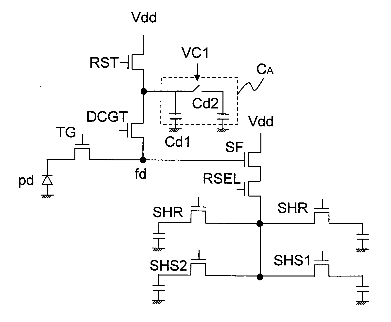
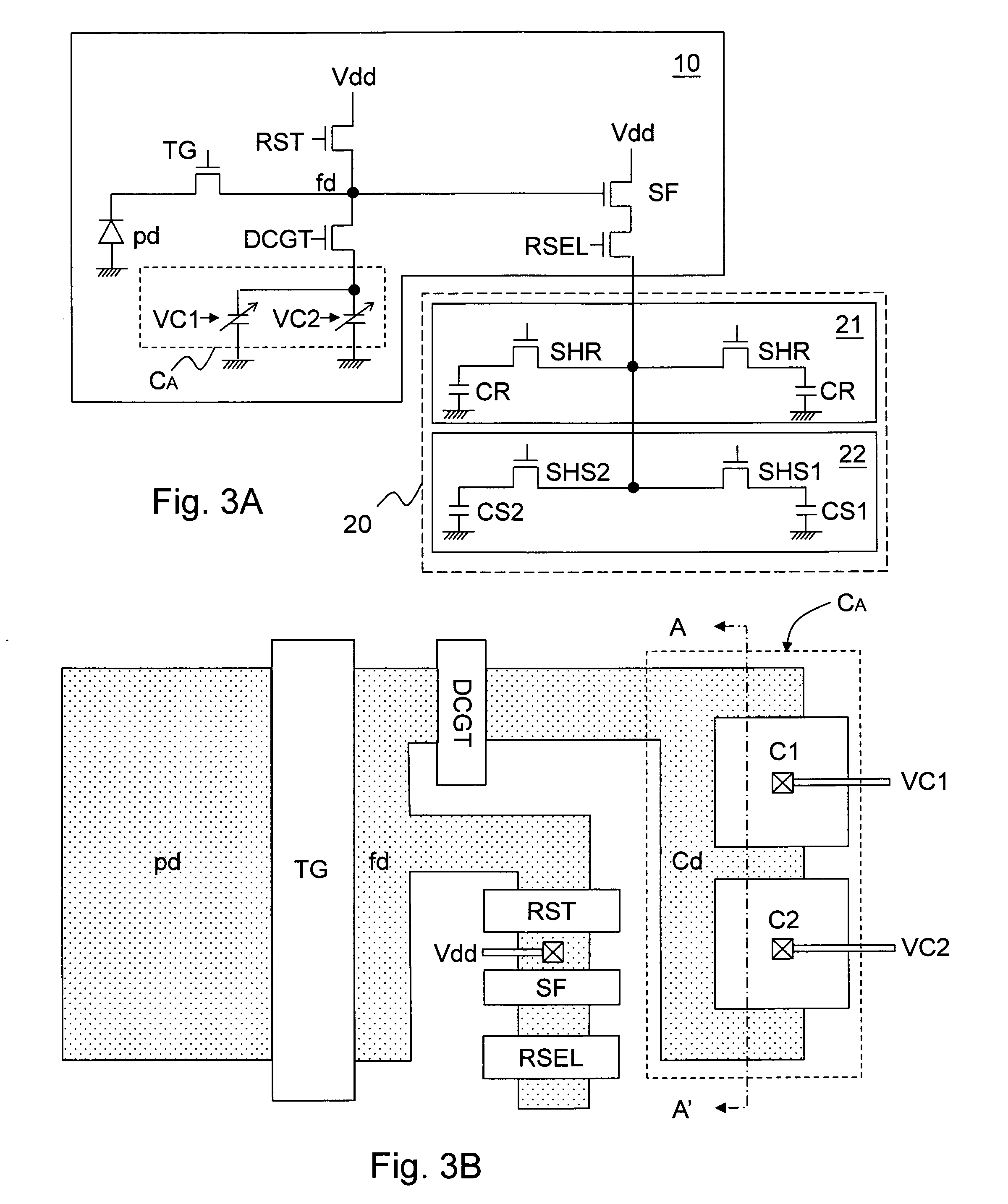
[0031]FIGS. 3A-3L show the first embodiment of the present invention. The high dynamic range imager circuit according to the present invention includes an image sensor device 10, which is formed in a first conductive type substrate, for example but not limited to a P-type semiconductor substrate; and a signal reading circuit 20. Referring to FIG. 3A, which shows a circuit diagram of this embodiment, the image sensor device 10 includes: a photosensor unit pd, for example but not limited to a photodiode, a photogate, or a photoconductor, which is used for receiving a light signal to generate and accumulate photo-generated charges; a floating diffusion node fd for storing floating diffusion charges; a transfer gate, which is a transfer transistor TG in this embodiment, and is coupled between the photosensor unit pd and the floating dif...


PUM


Abstract

The present invention discloses a high dynamic range imager circuit and a method for reading high dynamic range image with an adaptive conversion gain. The high dynamic range image circuit includes a variable capacitor. The capacitance of the variable capacitor is adjusted according to sensed light intensity or by internal feedback control, to adaptively adjust the conversion gain of the high dynamic range image circuit as it reads a signal which relates to a pixel image sensed by an image sensor device. In each cycle, the signal can be read twice or more with different dynamic ranges, to enhance the accuracy of the signal.

Description

CROSS REFERENCE[0001]The present invention claims priority to TW 100112180, filed on Apr. 8, 2011.BACKGROUND OF THE INVENTION[0002]1. Field of Invention[0003]The present invention relates to a high dynamic range imager circuit and a method for reading a high dynamic range image; particularly, it relates to such circuit and method wherein a conversion gain for reading an image is adaptively adjusted by adjusting a variable capacitor.[0004]2. Description of Related Art[0005]FIG. 1 shows a prior art high dynamic range image sensor device, which is disclosed by U.S. Pat. No. 7,075,049. As shown in FIG. 1, the high dynamic range image sensor device includes a dual conversion gain transistor (DCGT) and a capacitor CA for switching the image reading conversion gain, in additional to the four transistors in a conventional 4T image sensor device . FIGS. 2A-2B and FIGS. 2C-2D are schematic diagrams showing charge levels at critical nodes of the high dynamic range image sensor device shown in ...

Claims


Application Information

Patent Timeline
Patent Type & Authority Applications(United States)
IPC IPC(8): H01L27/148
CPCH01L27/14609H04N5/3559H01L27/14643H04N5/37452H04N25/59H04N25/771
Inventor YEN, WEN-CHENGCHEN, CHING-WEILEE, CHAO-CHI
Owner SK HYNIX INC
Why Eureka
Try Eureka