Light-emitting device, light bulb shaped lamp and lighting apparatus

a technology of light-emitting devices and light-emitting elements, which is applied in the direction of semiconductor devices for light sources, lighting and heating apparatus, discharge tubes luminescnet screens, etc., can solve the problems of difficult for the conventional led light bulb to achieve the light-distribution property, the heat generated at the led is not effectively dissipated, and the led is blocked by the case, etc., to suppress the degradation of the semiconductor light-emitting element, the effect of effective heat generation

Inactive Publication Date: 2012-10-11
PANASONIC CORP
View PDF1 Cites 24 Cited by
  • Summary
  • Abstract
  • Description
  • Claims
  • Application Information

AI Technical Summary

Benefits of technology

[0021]According to the light-emitting device of the present invention, it is possible to effectively conduct the heat generated at the semiconductor light-emitting element and the heat can be effectively dissipated. Therefore, it is possible to suppress the degradation of the semiconductor light-emitting element.

Problems solved by technology

However, in the conventional LED light bulb, the LED module is provided on the surface of the metal case in the globe, and thus the light emitted from the LED toward the base is blocked by the case.
As described above, the light emitted from the conventional LED light bulb spreads differently from the light emitted from incandescent light bulbs which is omnidirectionally distributed, and thus it is difficult for the conventional LED light bulb to achieve the light-distribution property same as that of incandescent light bulbs.
However, in this configuration, the case which functions as a heat sink is not used, thereby causing a problem that the heat generated at the LED is not effectively dissipated.

Method used


Image

  • Light-emitting device, light bulb shaped lamp and lighting apparatus
  • Light-emitting device, light bulb shaped lamp and lighting apparatus
  • Light-emitting device, light bulb shaped lamp and lighting apparatus

Examples


Embodiment Construction

[0033]The following shall describe the LED module, the light bulb shaped lamp, and the lighting apparatus according to the embodiment of the present invention with reference to the drawings. However, the present invention is defined by Claims. Accordingly, among the components in the embodiment, the components not described in Claims are not necessary for solving the problem of the present invention but included for a preferable embodiment. Note that, the diagrams are schematic diagrams, and illustration is not necessarily strictly accurate. In the drawings, the same reference numerals are assigned to the same components, and the description for these components shall be omitted or simplified.

(Overall Structure of Light Bulb Shaped Lamp)

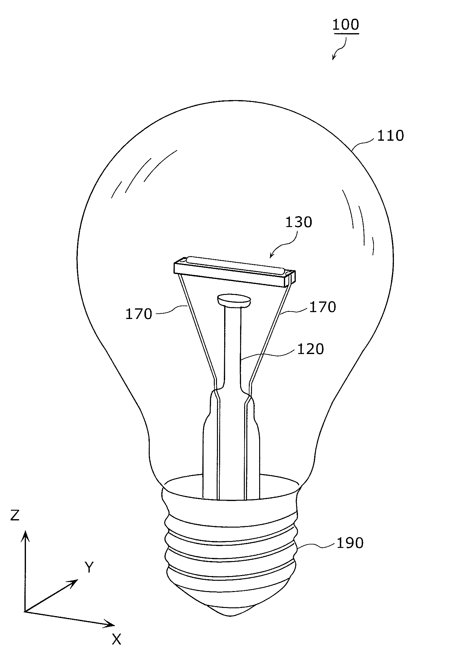
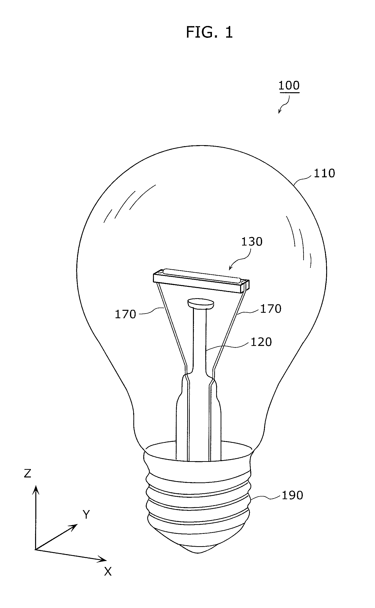
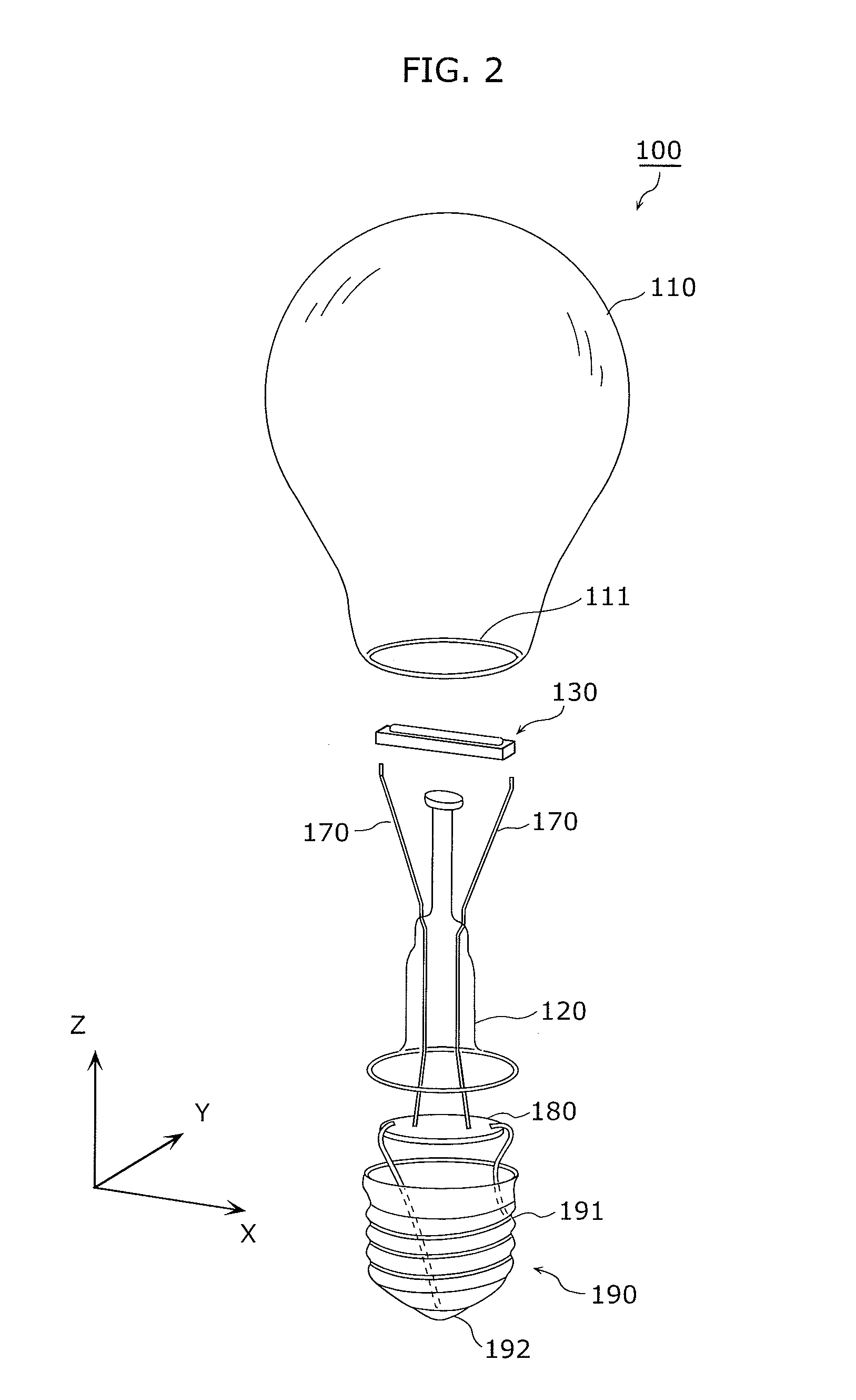
[0034]The overall structure of the light bulb shaped lamp 100 according to the embodiment of the present invention shall be described with reference to FIGS. 1 to 3.

[0035]FIG. 1 is a diagrammatic perspective view of a light bulb shaped lamp according...


PUM


Abstract

A light-emitting device capable of effectively dissipating heat generated at an LED is provided. The light-emitting device according to the present invention includes: a base board and an LED chip mounted on the base board. The base board is a translucent base board made of a polycrystalline ceramic. A main region of the base board includes an element mounted region on which the LED chip is mounted, and an average grain size of the polycrystalline ceramic in the main region is between 10 μm and 40 μm inclusive. An end portion region of said base board is a region around an end portion, and an average grain size of the polycrystalline ceramic in the end portion region is preferably smaller than an average grain size of the polycrystalline ceramic in the element mounted region.

Description

TECHNICAL FIELD[0001]The present invention relates to a light bulb shaped lamp having a semiconductor light-emitting element and a lighting apparatus which includes the light bulb shaped lamp.BACKGROUND ART[0002]Compared to conventional illumination light source, light emitting diodes (LED) which are semiconductor light-emitting elements are small, have high efficiency and long product life. Recent market needs for saving energy and resource boosts the demand for light bulb shaped lamps using LEDs (hereafter simply referred to as “LED light bulb”) and lighting apparatuses including the LED light bulbs.[0003]Known properties of LEDs include reduced light output as temperature increases, leading to shorter product life. In response to this problem, a metal case is provided between semispherical globe and a base in a conventional LED light bulb so as to suppress the increase in the temperature of LED (for example, see Patent Literature 1). The metal case functions as a heat sink for ra...

Claims


Application Information

Patent Timeline
Patent Type & Authority Applications(United States)
IPC IPC(8): H01L33/62H01L33/48
CPCF21K9/135F21V3/00F21Y2101/02H01L2224/73265H01L2224/49107H01L2224/4945H01L2224/45144H01L2224/48091H01L2224/48137H01L2924/00014H01L2924/00F21K9/232F21Y2115/10
Inventor TAKEUCHI, NOBUYOSHIMATSUDA, TSUGIHIRONAGAI, HIDEOMIKI, MASAHIROUEMOTO, TAKAARI
Owner PANASONIC CORP
Why Eureka
Try Eureka