LCD light-reducing apparatus, and vehicle smart mirror using the same

a technology of light-reducing apparatus and vehicle smart mirror, which is applied in the direction of optical viewing, vehicle components, instruments, etc., can solve the problems of unsuitable vehicle exterior smart mirror application, comparatively slow response time, and low power consumption of lcd panel, so as to save power and light-reducing. the effect of low power consumption and fast response times

Inactive Publication Date: 2012-10-11
SODY
View PDF3 Cites 39 Cited by
  • Summary
  • Abstract
  • Description
  • Claims
  • Application Information

AI Technical Summary

Benefits of technology

[0013]According to the present invention, the following effects are expected apparently.
[0014]First, a light-reducing apparatus which is able to modulate light transmittance or light reflectance using an LCD panel without any polarizing film can be provided.
[0015]Second, a light-reducing apparatus which is able to uniformly modulate both polarized light and non-polarized light can be provided.
[0016]Third, because the power consumption of the LCD panel is low, a power saved light-reducing apparatus can be provided.
[0017]Fourth, light transmittance or light reflectance and the response time thereof can be arbitrarily controlled depending on changes in peripheral brightness using the grey scales and the fast response times of the LCD.
[0018]Fifth, even when the electric power is disconnected abruptly, the light transmittance or the light reflectance of the light-reducing apparatus can be maintained in bright state.

Problems solved by technology

Although these photo-chromic materials are advantageous because of their simple application, their response times are too slow to apply it to the vehicle smart mirrors.
However, such an ECM technique suffers from a comparatively slow response time in the range of ones to tens of seconds, making it unsuitable to apply it to the exterior smart mirrors for vehicles, etc.
However, when the polarizing films are used, a light transmittance depends on the azimuth angle of the polarization direction of incident light, and the light transmittance or a light reflectance may decrease undesirably due to the polarizer.
Hence, in the application of a vehicle smart mirror, the LCD mirror should be darken in an emergency of the electric power off, thus interfere the safe operation of a driver, consequently violate the international safety regulations for vehicle mirrors.
Consequently the absorption of incident light which is isotropically polarized cannot be maximized by using the same molecular-weight dyes due to its anisotropic arrangement in azimuth.
However, the formation of the ¼ wavelength polymeric liquid crystal film in the cells requires more complicated processes, and the light absorption depends on the azimuth angle of the polarization direction of the incident light.

Method used


Image

  • LCD light-reducing apparatus, and vehicle smart mirror using the same
  • LCD light-reducing apparatus, and vehicle smart mirror using the same
  • LCD light-reducing apparatus, and vehicle smart mirror using the same

Examples


Embodiment Construction

[0028]A preferred embodiment of the present invention, of an LCD light-reducing apparatus and a vehicle smart mirror using the same, is described below with reference to the drawings.

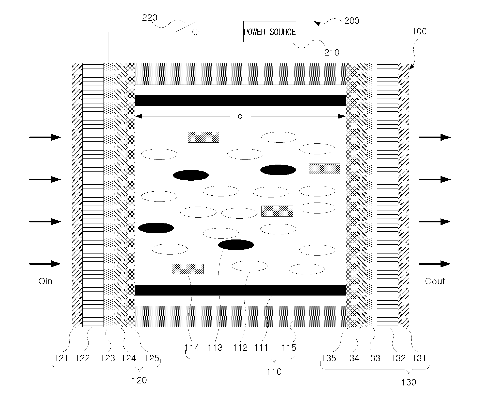
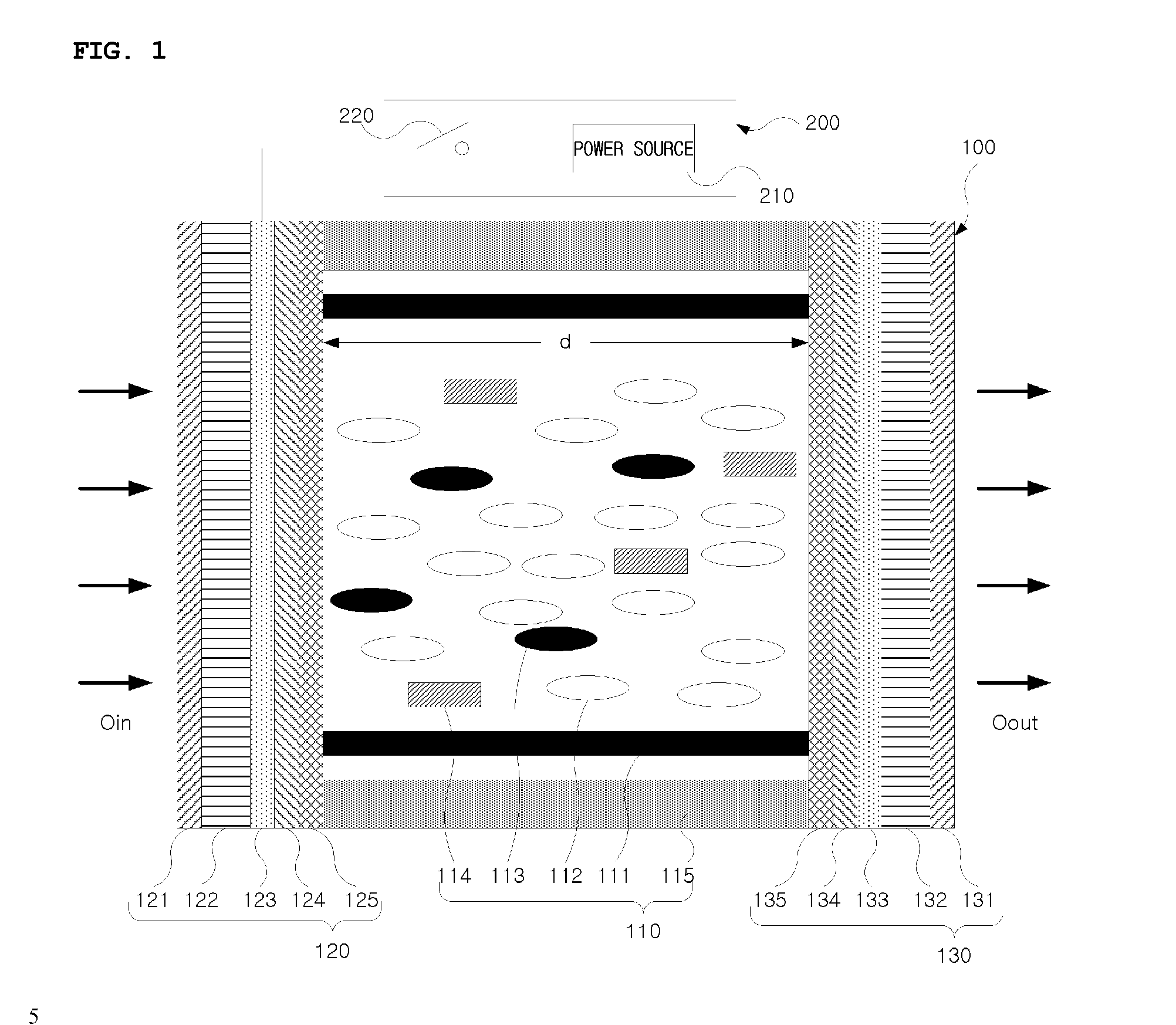
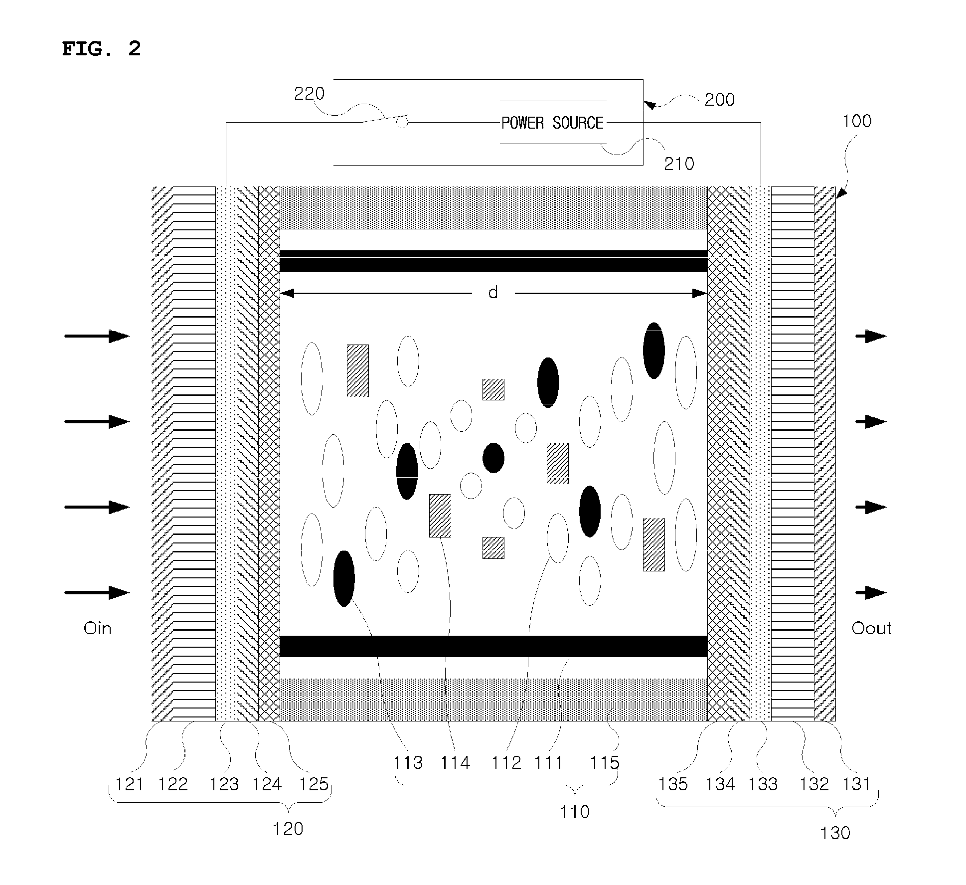
[0029]FIGS. 1 and 2 show a transmissive LCD light-reducing apparatus according to a first embodiment of the present invention, wherein FIG. 1 shows the case where power is not supplied, and FIG. 2 shows the case where it is supplied.

[0030]The LCD light-reducing apparatus according to the present invention includes a guest-host LCD panel having one or more liquid crystal cells 100 and a power supply unit 200 for applying an electric field to respective liquid crystal cells 100 of the LCD panel. The liquid crystal cells 100 each include a liquid crystal layer 110 and two substrate layers 120 and 130 which are faced on both outer surfaces of the liquid crystal layer 110.

[0031]The liquid crystal layer 110 includes spacers 111 which maintain the gap between the two substrate layers 120 and 130, and is filled...


PUM

PropertyMeasurementUnit
transmittanceaaaaaaaaaa
azimuth anglesaaaaaaaaaa

Abstract

The present invention relates to an LCD light-reducing apparatus, and to a vehicle smart mirror using the same, which are to be applied to the interior rear-view mirror or exterior side-view mirrors of a vehicle to protect the vision of the driver of the vehicle from bright lights or glares coming from behind him during nighttime drive. The LCD light-reducing apparatus according to the present invention comprises an LCD panel including at least one liquid crystal cell, and a power supply device for supplying a sufficient electric field to the LCD panel. The LCD cell includes a liquid crystal layer; and two substrate layers opposite one another with the liquid crystal layer at center thereof. The liquid crystal layer is filled with a compound including negative dielectric anisotropic nematic liquid crystals, a chiral material for inducing a cholesteric phase of the nematic liquid crystals to have a pitch of 1 to 4 times the cell gap of the liquid crystal layer, and dichromic dyes for being rearranged parallel to the nematic liquid crystals to transmit or absorb light in accordance with whether the electric field is applied or not. The substrate layer includes a tilted homeotropic alignment layer for arranging the respective nematic liquid crystals and dichromatic dyes in a first arrangement that is vertically aligned to the surface of the substrate layer, and an electrode for generating a sufficient electric field that passes through the liquid crystal layer to rearrange the nematic liquid crystals and dichromatic dyes in a second arrangement that is different from the first arrangement.

Description

TECHNICAL FIELD[0001]The present invention relates to an LCD (Light Crystal Display) light-reducing apparatus for use in a vehicle smart mirror, and more particularly to an LCD light-reducing apparatus and a vehicle smart mirror using the same, which may be applied to an interior rear view mirror or exterior side view mirrors of vehicles in order to prevent glare and protect the vision of a driver from bright light emitted from behind during nighttime driving.BACKGROUND ART[0002]Typically a light-reducing apparatus is variously applied to ski goggles, sunglasses, vehicle smart mirrors for protecting the driver of a vehicle from glare, and windows for modulating light transmittance. In the case of sunglasses or ski goggles, the light-reducing apparatus is mainly manufactured using photo-chromic materials. Although these photo-chromic materials are advantageous because of their simple application, their response times are too slow to apply it to the vehicle smart mirrors. On the other...

Claims


Application Information

Patent Timeline
Patent Type & Authority Applications(United States)
IPC IPC(8): G02F1/1335
CPCB60R1/088G02F1/1396G02F2203/06G02F2001/133742G02F2001/13712G02F1/13737G02F1/133742G02F1/13712
Inventor LEE, JONG-CHEON
Owner SODY
Why Eureka
Try Eureka