Optical fiber connector ferrule having open fiber clamping grooves

Active Publication Date: 2012-10-11
SENKO ADVANCED COMPONENTS
View PDF6 Cites 60 Cited by
  • Summary
  • Abstract
  • Description
  • Claims
  • Application Information

AI Technical Summary

Benefits of technology

[0028]In one embodiment, the ferrule body is made of a metal material, which may be chosen to have high stiffness (e.g., stainless steel), chemical inertness (e.g., titanium), high temperature stability (nickel alloy), low thermal expansion (e.g., Invar), or to match thermal expansion to other materials (e.g., Kovar for matching glas

Problems solved by technology

These devices couple fibers in an end-to-end relationship, with the coupling being one source of light loss.
The injection molded structure inherently does not hold tolerance well.
Polymers are also susceptible to creep and thermal expansion/contraction over longer periods of time.
The epoxy shrinks upon curing, which leads to bending of the plastic ferrule.
Further, epoxy creeps over time, leading to pistoning or retracting of the optical fiber ends (which are pushed against the ends of adjoini

Method used


Image

  • Optical fiber connector ferrule having open fiber clamping grooves
  • Optical fiber connector ferrule having open fiber clamping grooves
  • Optical fiber connector ferrule having open fiber clamping grooves

Examples


Embodiment Construction

[0030]This invention is described below in reference to various embodiments with reference to the figures. While this invention is described in terms of the best mode for achieving this invention's objectives, it will be appreciated by those skilled in the art that variations may be accomplished in view of these teachings without deviating from the spirit or scope of the invention.

[0031]The present invention provides a ferrule for an optical fiber connector, which overcomes many of the drawbacks of the prior art ferrules and connectors. The ferrule in accordance with the present invention provides an optical fiber connector having a optical fiber ferrule, which results in low insertion loss and low return loss, which provides ease of use and high reliability with low environmental sensitivity, and which can be fabricated at low cost.

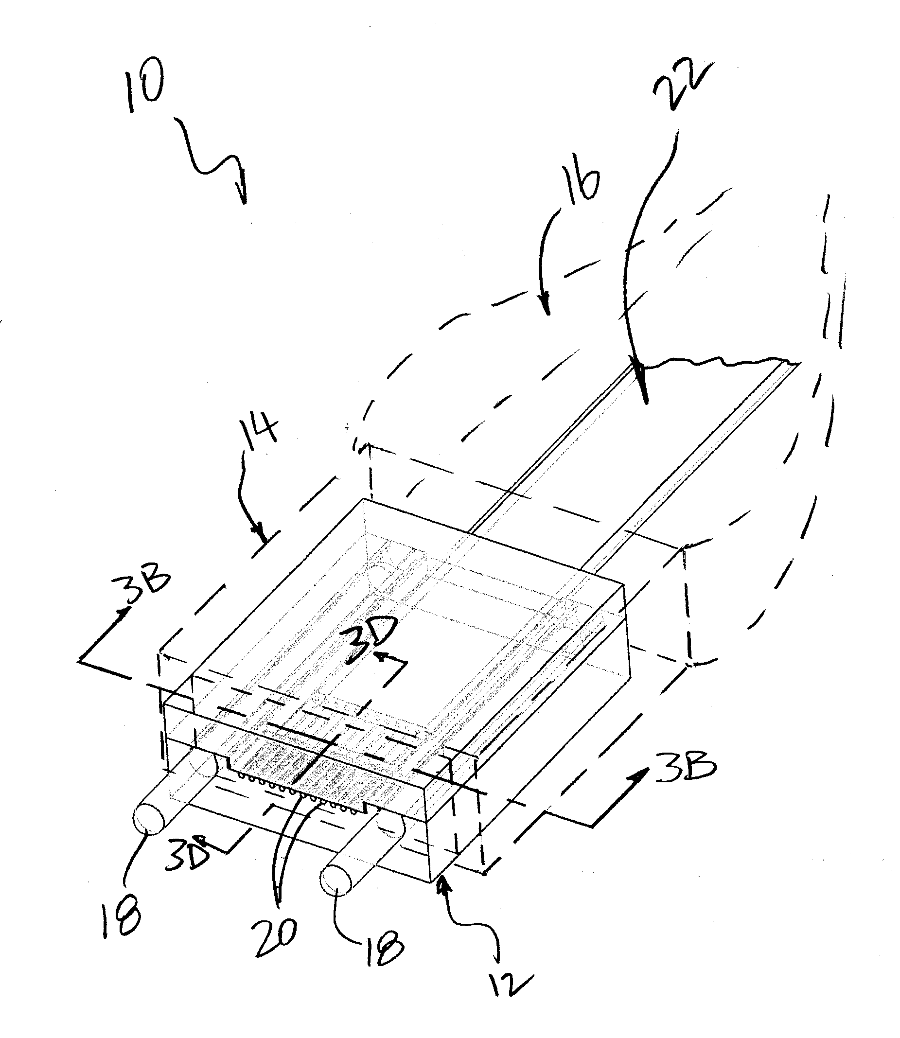
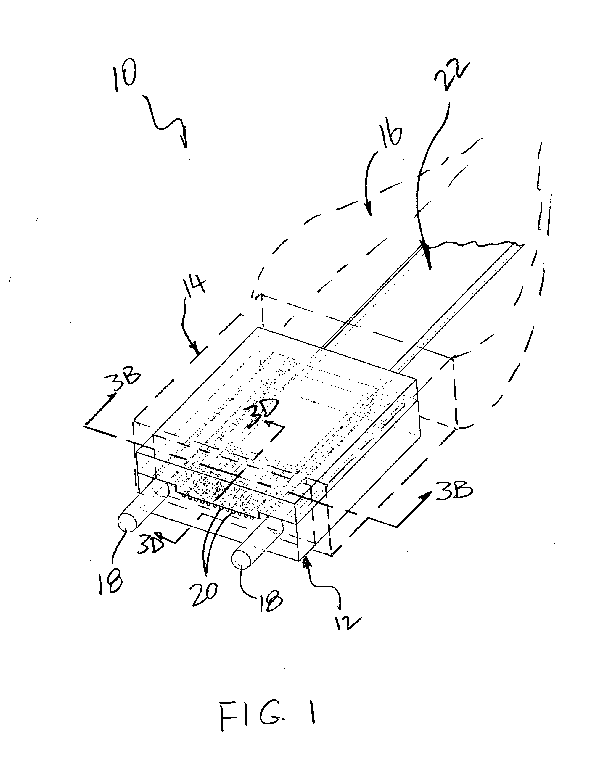
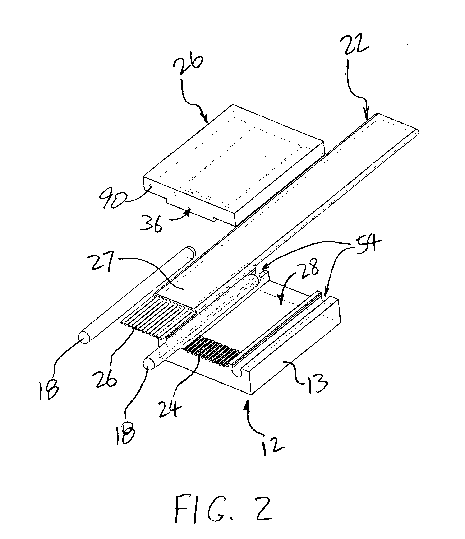
[0032]FIG. 1 illustrates a perspective view of an optical fiber assembly 10 having an assembly of components including a ferrule 12 in accordance with o...


PUM

PropertyMeasurementUnit
Lengthaaaaaaaaaa
Diameteraaaaaaaaaa
Widthaaaaaaaaaa

Abstract

A ferrule for an optical fiber connector having open fiber clamping grooves. The ferrule has a body having a plurality of open grooves for clamping the terminating end sections of optical fibers. At least a section of the longitudinal opening of the groove is provided with opposing lips to provide a clamping effect. The width of the longitudinal opening defined between the lips along at least a section of the grooves is narrower than the diameter of the optical fibers to create a tight fit. The grooves and the width of the longitudinal groove openings are shaped and sized to retain the fibers without any clearance to allow for movement of the fiber relative to the groove. Similar grooves may be provided in the ferrule body for alignment guide pins. The grooves are precision formed by high throughput processes, such as stamping and extrusion.

Description

PRIORITY CLAIM[0001]This application claims the priority of U.S. Provisional Patent Application No. 61 / 472,133 filed on Apr. 5, 2011, which is fully incorporated by reference as if fully set forth herein. All publications noted below are fully incorporated by reference as if fully set forth herein.BACKGROUND OF THE INVENTION[0002]1. Field of the Invention[0003]The present invention relates to optical fiber connectors, in particular ferrules in optical fiber connectors.[0004]2. Description of Related Art[0005]There are many advantages of transmitting light signal via optical fiber waveguides and the use thereof is diverse. Single or multiple fiber waveguides may be used simply for transmitting visible light to a remote location. Complex telephony and data communication systems may transmit multiple specific optical signals. These devices couple fibers in an end-to-end relationship, with the coupling being one source of light loss. Precision alignment of two polished ends of fibers is...

Claims


Application Information

Patent Timeline
IPC IPC(8): G02B6/36B21D22/00
CPCG02B6/364G02B6/3858G02B6/3885G02B6/3839G02B6/38G02B6/3676
Inventor LI, SHUHEVALLANCE, ROBERT RYANBARNOSKI, MICHAEL K.
Owner SENKO ADVANCED COMPONENTS
Why Eureka
Try Eureka