Power generating apparatus of renewable energy type

a technology of renewable energy and power generation equipment, which is applied in the manufacture of final products, marine propulsion, vessel construction, etc., can solve the problems of increasing the size of the equipment, increasing the weight and cost of the gearbox, and increasing the heat loss of the generator, so as to achieve high efficiency and high efficiency

Inactive Publication Date: 2012-10-11
MITSUBISHI HEAVY IND LTD
View PDF5 Cites 21 Cited by
  • Summary
  • Abstract
  • Description
  • Claims
  • Application Information

AI Technical Summary

Benefits of technology

[0052]Further, one of the operating-oil circulation line and the operating-oil branch line is divided into the first piping supported on the nacelle side and the second piping supported on the tower side, and the first piping and the second piping are arranged relatively rotatable with each other by means of the connection part having the swivel structure. Therefore, even when the nacelle turns, the fluid can communicate smoothly between the first piping on the nacelle side and the second piping on the tower side.
[0055]In the one aspect of the present invention, the cooling medium used to cool the operating oil, is cooled by heat exchange with the cool water source which is one of sea water, lake water, river water and groundwater around the base portion of the tower and thus, the cooling medium can be cooled by cool water with high efficiency.
[0056]Further, one of the operating-oil line and the cooling-medium line is divided into the first piping supported on the nacelle side and the second piping supported on the tower side and the first piping and the second piping are arranged relatively rotatable with each other by means of the connection part having the swivel structure. Therefore, even when the nacelle turns, the fluid can communicate smoothly between the first piping on the nacelle side and the second piping on the tower side.
[0057]In the other aspect of the present invention, the operating oil is cooled by heat exchange with cool water source which is one of sea water, lake water, river water and groundwater around the base portion of the tower. Therefore, the operating oil can be cooled by the cool water source with high efficiency.

Problems solved by technology

In the case of the power generating apparatus of renewable energy type equipped with a mechanical gearbox, weight and cost of the gearbox tends to increase with increase in size of the apparatus.
Meanwhile, with increased output of the generator produced by the larger wind turbine generator, heat loss from the generator increases.
In the wind turbine generator having the hydraulic transmission formed by the hydraulic pump and the hydraulic motor, in addition to the heat loss from the generator, there is heat loss from the hydraulic transmission.

Method used


Image

  • Power generating apparatus of renewable energy type
  • Power generating apparatus of renewable energy type
  • Power generating apparatus of renewable energy type

Examples


first embodiment

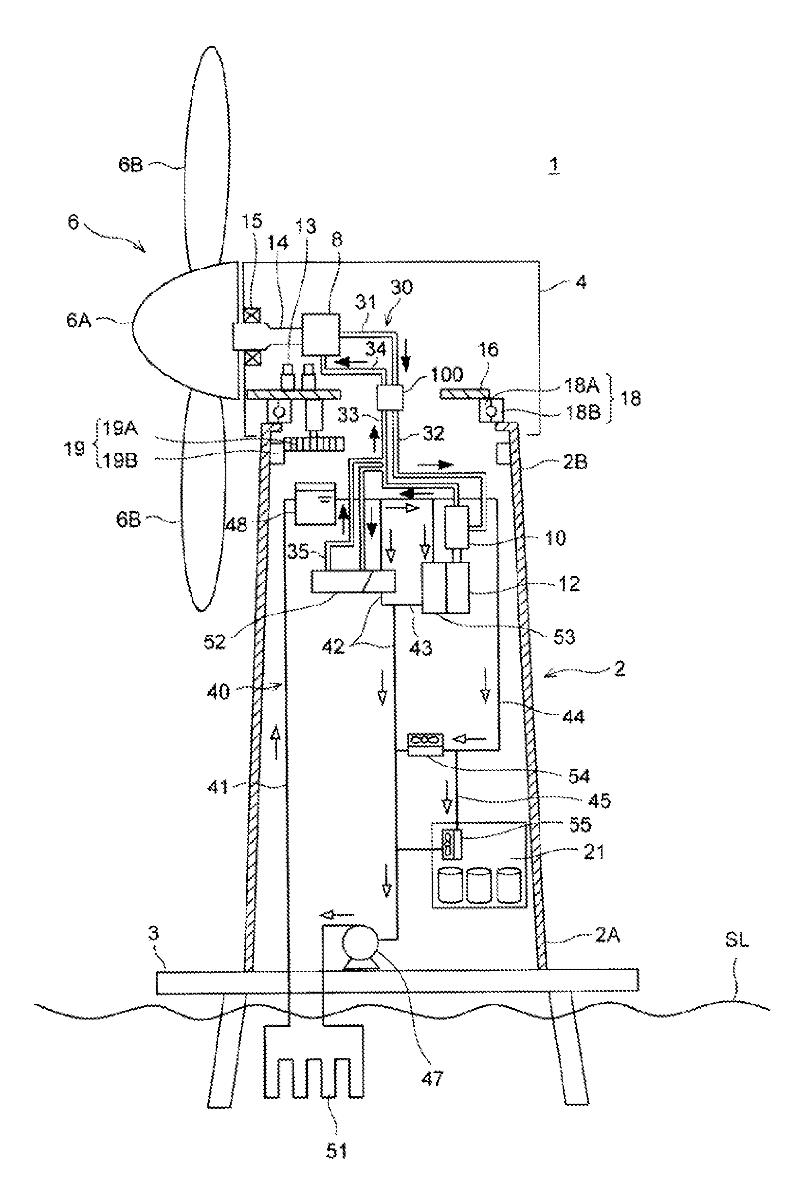
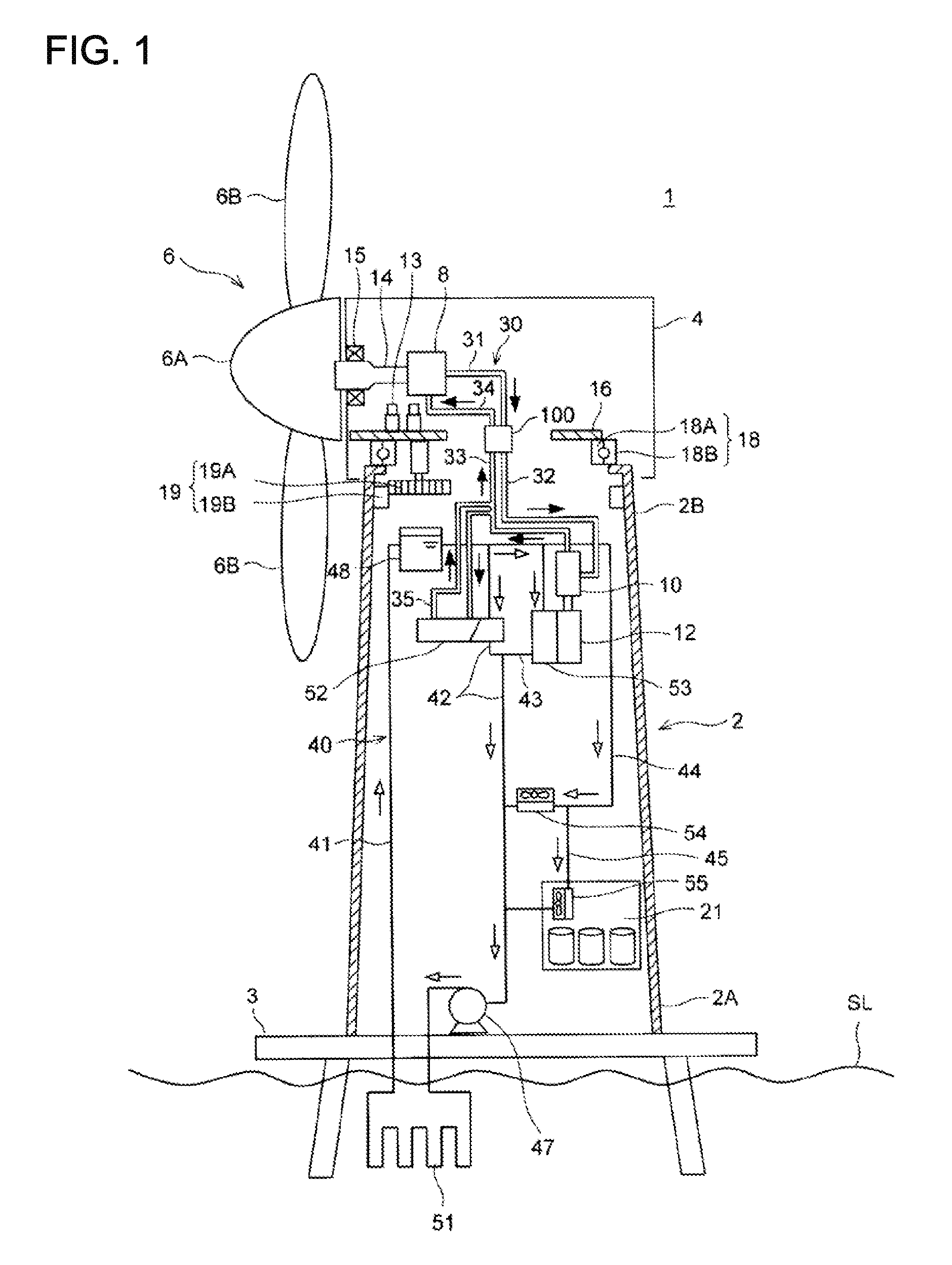
[0078]In a first embodiment, a wind turbine generator is described as an example of a power generating apparatus of renewable energy type. FIG. 1 shows a general structure of the wind turbine generator in relation to the first embodiment.

[0079]As shown in FIG. 1, the wind turbine generator 1 is mainly formed by a tower 2, a nacelle 4 provided at a tip portion 2B of the tower 2, a rotor 6 being rotated by wind, a hydraulic pump 8, a hydraulic motor 10 and a generator 12 being coupled to the hydraulic motor 10.

[0080]The wind turbine generator 1 shown in FIG. 1 is an offshore wind turbine generator installed at a sea level SL. However, this is not limitative and the wind turbine generator 1 may be installed on shore where cool water source is available nearby.

[0081]The tower 2 is installed upright on a base 3 which is arranged at a height near the seal level. The tower 2 extends upward from a base portion 2A facing the base 3 to the tip portion 2B in a vertical direction. The nacelle 4...

second embodiment

[0159]A second preferred embodiment is explained in reference to FIG. 11. FIG. 11 shows a general structure of a wind turbine generator in relation to the second embodiment of the present invention. The wind turbine generator 1 of the second embodiment is substantially the same as that of the first embodiment, except for configurations of the hydraulic transmission and the operating-oil line 30. Thus, mainly the configurations different from the first embodiment are explained and the components already described in the first embodiment are indicated by the same reference numbers in FIG. 11 and are not explained further. In FIG. 11, the nacelle swivel mechanism 19 and the yaw driving mechanism 13 are not shown.

[0160]In the wind turbine generator 1 of the second embodiment, the hydraulic motor 10 and the generator 12 are supported on the nacelle side and the intermediate heat exchanger 52 is supported on the tower side.

[0161]The operating-oil line 30 includes an operating-oil circulat...

third embodiment

[0170]A third preferred embodiment is explained in reference to FIG. 12. FIG. 12 shows a general structure of a wind turbine generator in relation to the third embodiment of the present invention.

[0171]The wind turbine generator 1 of the third embodiment is substantially the same as that of the first embodiment, except for configurations of the hydraulic transmission and the operating-oil line 30. Thus, mainly the configurations different from the first embodiment are explained and the components already described in the first embodiment are indicated by the same reference numbers in FIG. 12 and are not explained further. In FIG. 12, the nacelle swivel mechanism 19 and the yaw driving mechanism 13 are not shown.

[0172]In the wind turbine generator 1 of the third embodiment, the hydraulic motor 10 and the generator 12 are arranged in the nacelle 4 and the intermediate heat exchanger 52 is arranged in the nacelle 4 as well.

[0173]The operating-oil line 30 includes an operating-oil circu...


PUM


Abstract

A power generating apparatus of renewable energy type includes a tower, a nacelle which is supported rotatably by a tip portion of the tower; a main shaft rotatable with a blade; a hydraulic pump which is housed in the nacelle and is driven by rotation of the main shaft; a hydraulic motor which is driven by operating oil supplied from the hydraulic pump; a generator which is coupled to the hydraulic motor; an operating-oil line which is provided between the hydraulic pump and the hydraulic motor and through which the operating oil circulates; a cooling-medium line through which cooling medium for cooling the operating oil circulates via an intermediate heat exchanger; and a main heat exchanger which cools the cooling medium by heat exchange with cool water source around a base portion of the tower, and one of the operating-oil line.

Description

[0001]The present Application is a Bypass Continuation of International Application No. PCT / JP2011 / 071673, filed on Sep. 22, 2011; which Application claims priority benefit of PCT / JP2011 / 058647, filed Apr. 5, 2011 and PCT / JP2011 / 068284, filed Aug. 10, 2011.TECHNICAL FIELD[0002]The present invention relates to a power generating apparatus of renewable energy type which transmits rotation energy of a rotor from a renewable energy source to a generator, particularly a power generating apparatus of a renewable energy type having a function of cooling a hydraulic transmission.BACKGROUND ART[0003]From the perspective of preserving the global environment, power generating apparatuses of a renewable energy type such as a wind turbine generator using wind power and a tidal generator using tidal current, river current or ocean current energy are becoming popular. To improve power generation efficiency, it is desired to increase the size of the power generating apparatus of the renewable energ...

Claims


Application Information

Patent Timeline
Patent Type & Authority Applications(United States)
IPC IPC(8): F01D5/08
CPCF03D11/00F03D11/0008F03D11/005Y02E10/726F28D1/022Y02E10/722F05B2260/20F05B2230/61F05B2240/916F05B2240/95F03D13/10F03D80/60F03D80/70F03D80/80Y02E10/72Y02E10/727Y02P70/50Y02P80/10F03D80/00Y02E10/728
Inventor AKASHI, YUMATSUO, TAKESHISATO, SHINSUKEKAMEDA, TAKURO
Owner MITSUBISHI HEAVY IND LTD
Why Eureka
Try Eureka