Particle simulator and method of simulating particles

a particle simulator and particle technology, applied in the field of particle simulator and particle simulation method, can solve the problems of increasing processing speed, affecting load balance, and inconvenient situation, and achieve the effect of reducing the memory size used

Inactive Publication Date: 2012-10-11
JAPAN AGENCY FOR MARINE-EARTH SCIENCE AND TECHNOLOGY
View PDF0 Cites 10 Cited by
  • Summary
  • Abstract
  • Description
  • Claims
  • Application Information

AI Technical Summary

Benefits of technology

[0023]The particle simulator and the method of simulating particles according to the present invention, can reduces the memory size used during DEM calculation of particles having a particle diameter distribution by a shared-memory parallel computer.

Problems solved by technology

Specifically, if the process of storing particles into cells by looping the particle numbers is performed through single-instruction multiple-data (SIMD) parallel processing, competitive writing occurs in the memory when two or more particles are stored in the same cell, which is an extremely inconvenient situation.
Such a problem of competitive writing in the memory also occurs in particles having a uniform diameter if a plurality of particles is included a single cell.
However, if there is a particle diameter distribution, a distribution of the particles contained in a single cell is wide in itself, causing an even greater problem in increasing the processing speed by parallelization and vectorization.
Therefore, the load balance tends to be disturbed.
Accordingly, there is a problem of increasing a required volume of memory to perform DEM calculation.

Method used


Image

  • Particle simulator and method of simulating particles
  • Particle simulator and method of simulating particles
  • Particle simulator and method of simulating particles

Examples


Embodiment Construction

[0036]Embodiments of the present invention will be described below with reference to the accompanying drawings. The same components are represented by the same reference numerals without repeated description.

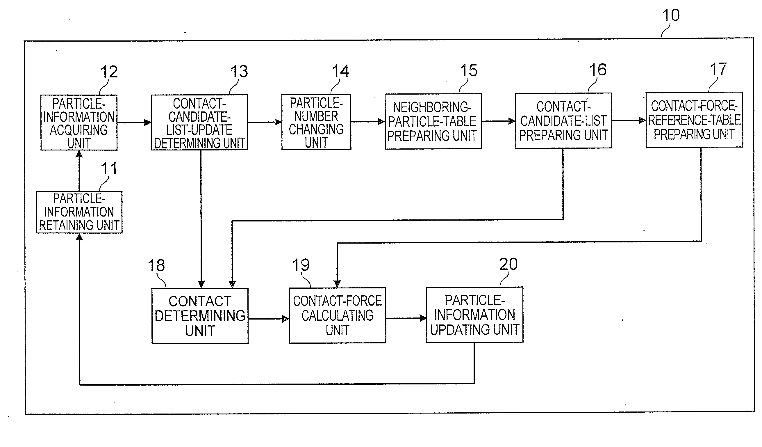
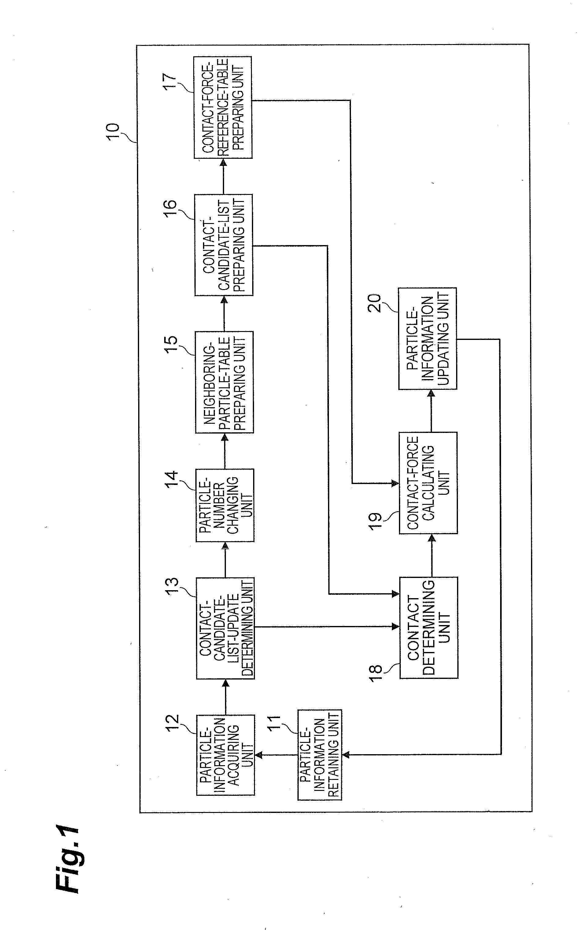
[0037]FIG. 1 is a functional block diagram of a particle simulator 10 according to an embodiment of the present invention. As illustrated in FIG. 1, the particle simulator 10 includes a particle-information retaining unit (input means and particle-information storing means) 11, a particle-information acquiring unit 12, a contact-candidate-list-update determining unit 13, a particle-number changing unit (assigning means) 14, a neighboring-particle-table preparing unit 15, a contact-candidate-list preparing unit (contact-candidate-particle selecting means and integrated-contact-candidate-number calculating means) 16, a contact-force-reference-table preparing unit (contact-force-reference-table preparing means) 17, a contact determining unit (contact-force calculating means) 18, a ...


PUM


Abstract

The memory size used in DEM calculation of particle having a particle diameter distribution is suppressed.
A particle simulator includes a particle-information retaining unit 11 holding particle information including position and velocity information of a particle group, a particle-number changing unit 14 assigning particle numbers specifying particles in an order in accordance with the positions of the particles to the particle, a contact-candidate-list preparing unit 16 selecting particle pairs of a target particle and another particle that may be in contact with the target particle, a contact determining unit 18 calculating contact forces generated between particles in the particle pairs on the basis of particle information and storing the contact forces in the contact-force tables, a contact-force calculating unit 19 extracting contact forces of particles having a diameter greater than particles from contact-force tables using a contact-force reference table 54, extracting contact forces of particles having a diameter smaller than the particles by specifying the storage positions in the contact-force tables using integrated-contact-candidate numbers s_jgi[i], and calculating the sum of the contact forces, and a particle-information updating unit 20 updating the particle information on the basis of the contact forces of the particle.

Description

BACKGROUND OF THE INVENTION[0001]1. Field of the Invention[0002]The present invention relates to a particle simulator and a method of simulating particles.[0003]2. Related Background Art[0004]A discrete element method (DEM), which has originated through research in civil engineering, has been applied in particle technology. Today, the method is in great demand as a numerical analysis method used to solve an extremely wide variety of problems associated with not only particles but also continuous subjects that cannot be readily treated. Many other methods of numerically tracking discrete particle motion, such as molecular dynamics (MD), lattice gas automation (LGA), and smoothed particle hydrodynamics, have also been developed, in addition to the DEM. The DEM has a wide range of application compared to the other numerical particle analysis methods because the calculation of determining interparticle forces in consideration of geometric information of the particles, such as the size a...

Claims


Application Information

Patent Timeline
Patent Type & Authority Applications(United States)
IPC IPC(8): G06G7/48
CPCG06F2217/16G06F17/5009G06F30/20G06F2111/10
Inventor NISHIURA, DAISUKESAKAGUCHI, HIDE
Owner JAPAN AGENCY FOR MARINE-EARTH SCIENCE AND TECHNOLOGY
Why Eureka
Try Eureka