Eureka AIR delivers breakthrough ideas for toughest innovation challenges, trusted by R&D personnel around the world.

System for reducing oil beneath the ground

a technology of oil extraction and system, applied in the field of apparatus, systems and methods for extracting oil, can solve the problems of reducing the energy needed for steam generation, and reducing the production capacity of that particular zone, so as to and reduce the density and viscosity

Inactive Publication Date: 2012-10-18
SYAGD
View PDF5 Cites 7 Cited by
  • Summary
  • Abstract
  • Description
  • Claims
  • Application Information

AI Technical Summary

Benefits of technology

[0013]The preferred embodiment of the invention includes a system for cracking, upgrading and extracting oil from underground deposits is presented. The system includes a gasifier, an injection well and a production well. The gasifier creates high pressure, high temperature syngas. The high pressure, high temperature syngas flows through the injection well into a deposit of oil under the ground to crack and hydrogenate the oil to produce upgraded oil with a reduced density and viscosity. The producti

Problems solved by technology

Typically, methods are used in heavy oil or bitumen that are greater than 50 meters deep where it is no longer economic to recover the hydrocarbon by current surface mining technologies.
This method is far more environmentally benign than oil sands mining.
Although the separation between injector and producer wells are planned for 15 foot, some wells have as high as 30 foot gaps, reducing production capability from that particular zone.
Given the quantity of steam required for the SAGD, energy needed for the steam generation represents a substantial cost for the SAGD.
High costs relative to another option for the steam generation can prevent use of some options for the steam generation regardless of ability to provide desired criteria, such as with respect to the production of CO2.
In contrast to indirect heating with the boilers, prior direct combustion processes inject steam and CO2 together into the formation even though injection of the CO2 into the formation may not be desired or acceptable in all applications.
Regarding the water input requirements, inability to recycle all of the steam injected results from having to remove impurities such as sodium chloride from any recovered water prior to the recovered water being combined with other make-up water to feed any steam generation.
Even if available, expense of purchasing water can incur cost for the SAGD.

Method used


Image

  • System for reducing oil beneath the ground
  • System for reducing oil beneath the ground
  • System for reducing oil beneath the ground

Examples


Embodiment Construction

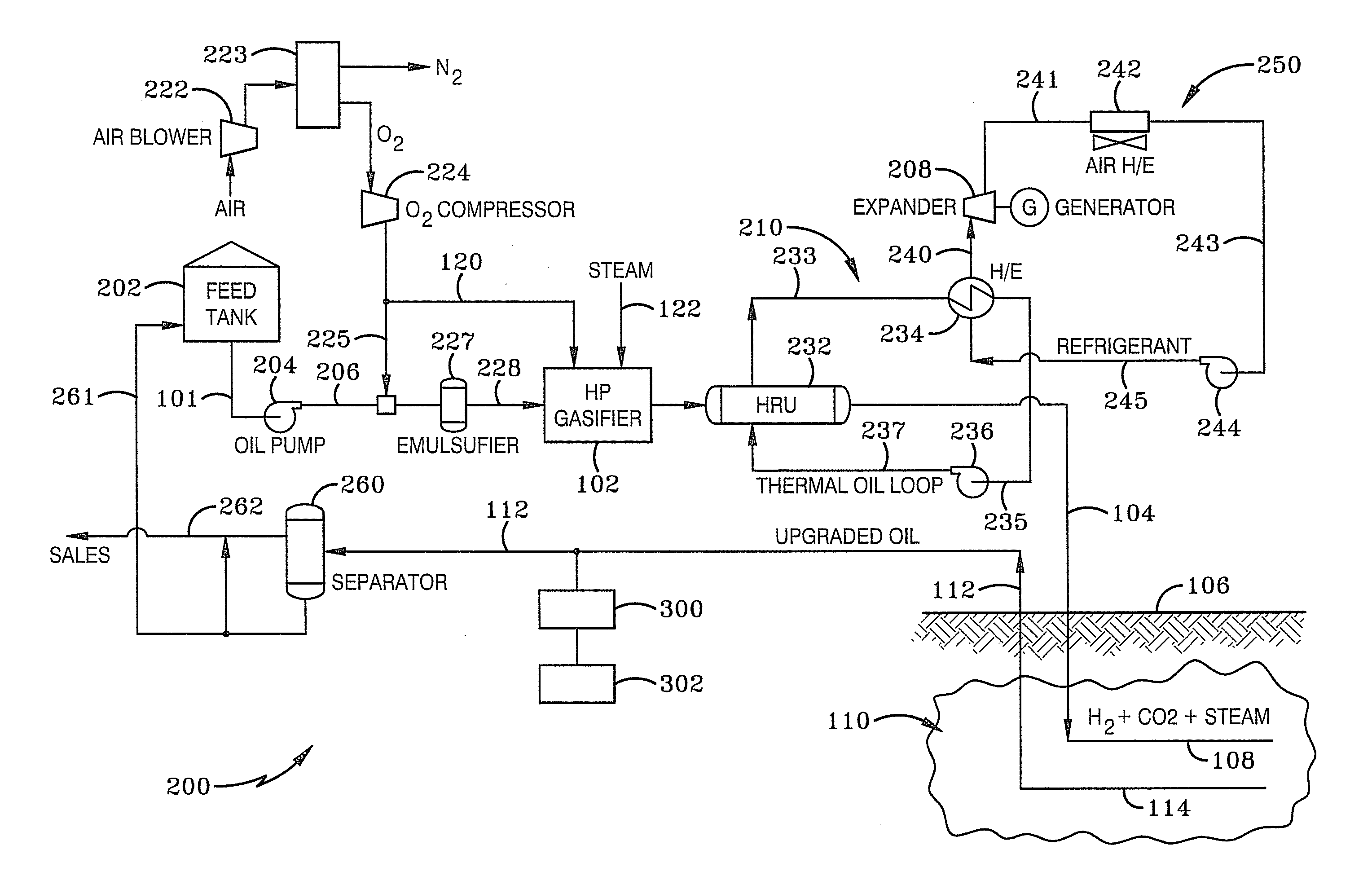
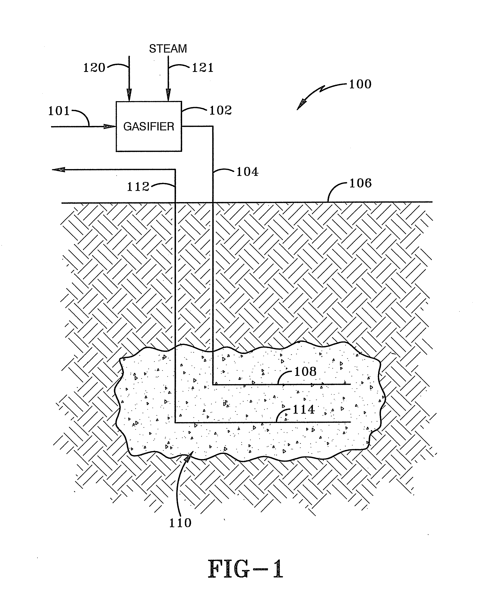
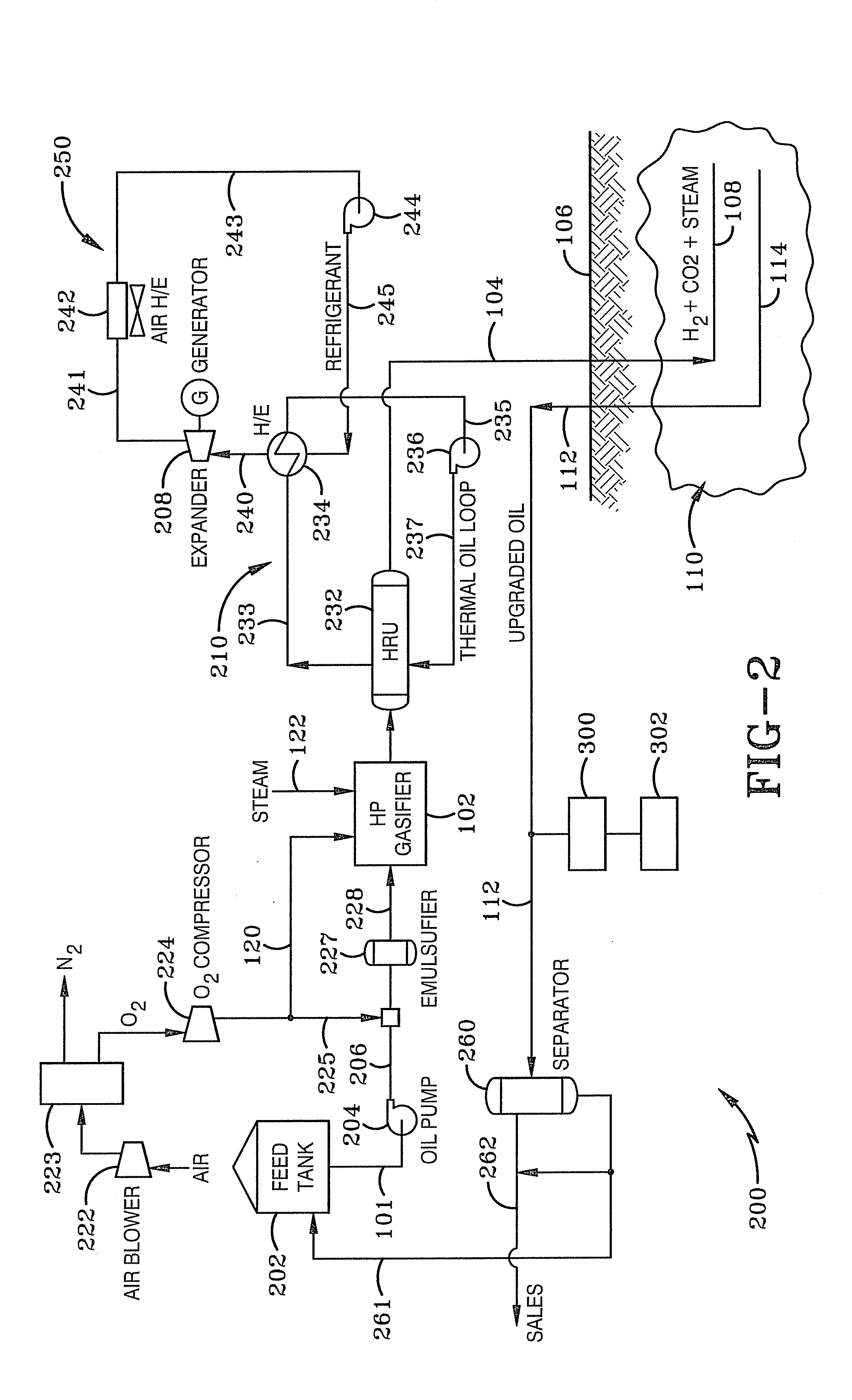
[0027]FIG. 1 illustrates a first configuration of the preferred embodiment of a system 100 for upgrading bitumen, heavy oil or another oil and extracting them from a reservoir 110. FIG. 1 illustrates a configuration of the preferred embodiment of the system that generates a syngas with a rather high temperature and pressure that is injected into an injection well. While it may not be practical to inject syngas with such high temperatures and pressures, this Figure is useful for understanding some of the novelty of the invention. After FIG. 1 is discussed, other figures that implement more detailed and more practical systems and methods such as those which reduce the temperature of the syngas before it is injected into a well are discussed further.

[0028]In FIG. 1, fuel is input to a high pressure gasifier 102 through a feed line 101 along with oxygen from line 120 and steam from line 121. The fuel is partially burned in the gasifier with the oxygen and steam to generate a high temper...


PUM


Abstract

A system and method for cracking, hydrogenating and extracting oil from underground deposits is presented. A system includes a gasifier, an injection well and a production well. The gasifier creates high pressure, high temperature syngas. The pressurized syngas flows through an injection well into a deposit of oil under the ground to crack and hydrogenate the oil to produce upgraded oil with a reduced density and viscosity. The production well of the system receives the reduced density and viscosity oil, transports it above the ground where it may be further separated into a portion that may be sold and a portion that can be gasified in the gasifier.

Description

CROSS REFERENCE TO RELATED APPLICATION[0001]This application claims priority from U.S. Provisional Application Ser. No. 61 / 476,480 filed Apr. 18, 2011; the disclosure of which is incorporated herein by reference.BACKGROUND OF THE INVENTION[0002]1. Field of Invention[0003]The current invention relates generally to apparatus, systems and methods for extracting oil. More particularly, the apparatus, systems and methods relate to extracting oil from underground deposits. Specifically, the apparatus, systems and methods provide for syngas assisted oil recovery, including at least partially cracking and hydrogenating the oil with syngas.[0004]2. Description of Related Art[0005]A variety of processes are used to recover viscous hydrocarbons such as heavy oil and bitumen from underground deposits. Typically, methods are used in heavy oil or bitumen that are greater than 50 meters deep where it is no longer economic to recover the hydrocarbon by current surface mining technologies. Depending...

Claims


Application Information

Patent Timeline
IPC IPC(8): E21B19/00
CPCE21B43/168
Inventor LOURENCO, JOSE J.P.MURPHY, JOHN GORDON
Owner SYAGD
Why Eureka
Eureka Blog
Learn More