Device having solid-liquid separation function, micro-tas device, and solid-liquid separation method

a technology of solid-liquid separation and micro-tas, which is applied in separation processes, laboratory glassware, instruments, etc., can solve the problems of difficult to simply install a filter in a micrometer-sized flow passage, -tas has a drawback, and the filter is difficult to mount in the flow passage without causing liquid leakage, etc., to achieve the effect of high rate of liquid flow with respect to the solid-liquid mixture, easy manufacturing and low cos

Inactive Publication Date: 2012-10-18
JOSHO GAKUEN EDUCATIONAL FOUND
View PDF4 Cites 16 Cited by
  • Summary
  • Abstract
  • Description
  • Claims
  • Application Information

AI Technical Summary

Benefits of technology

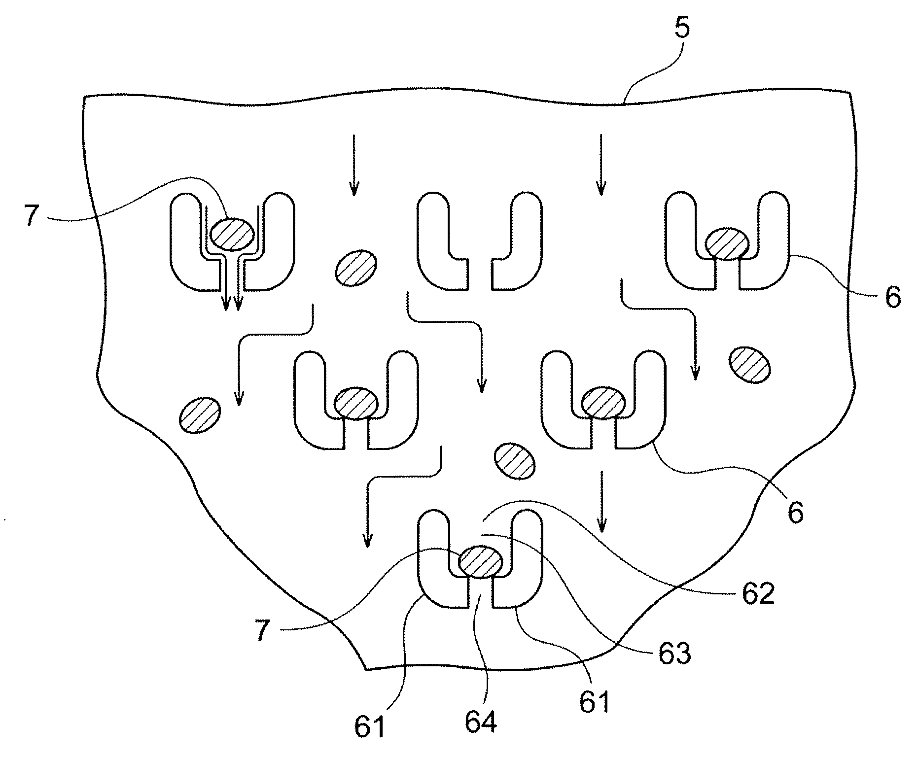
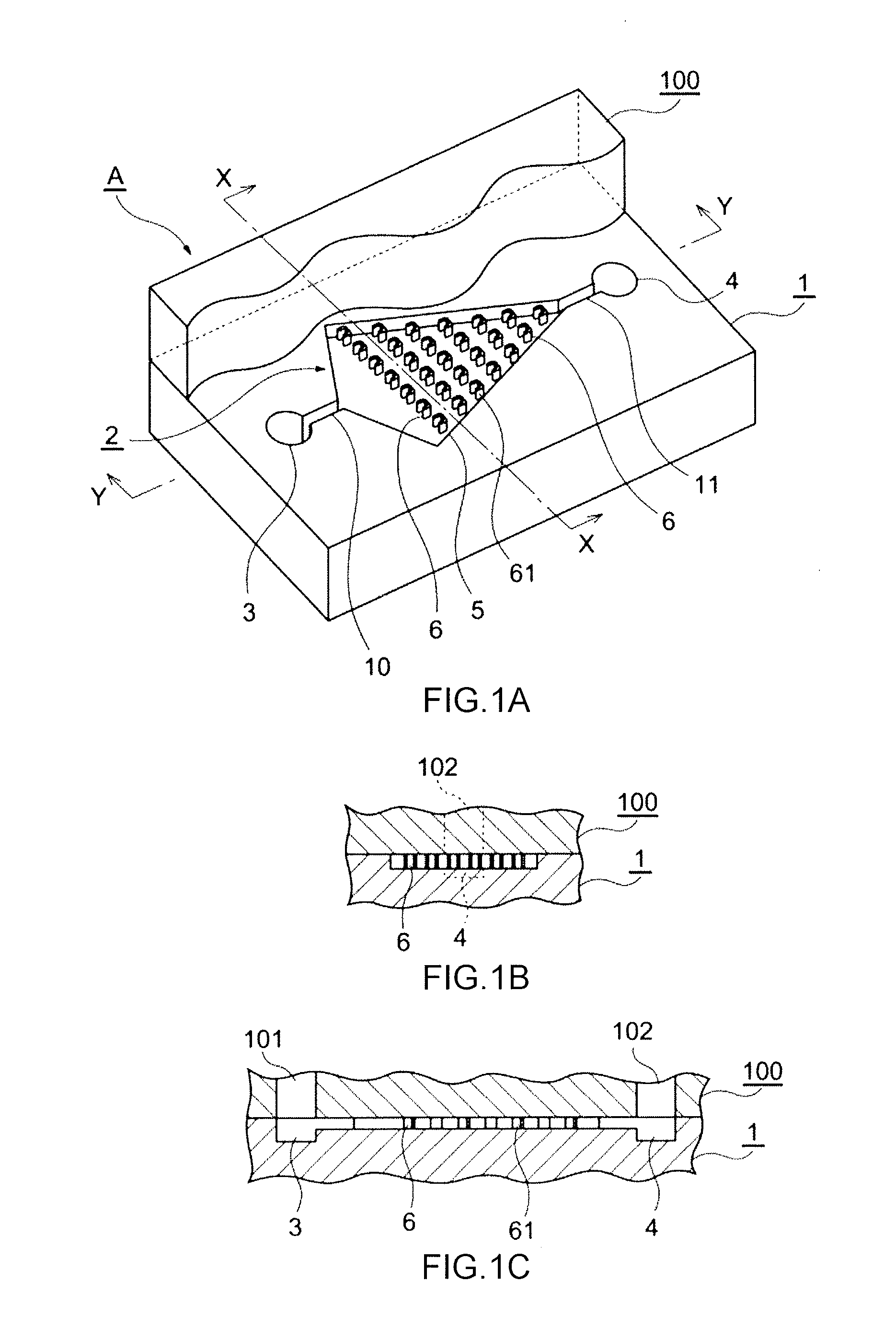
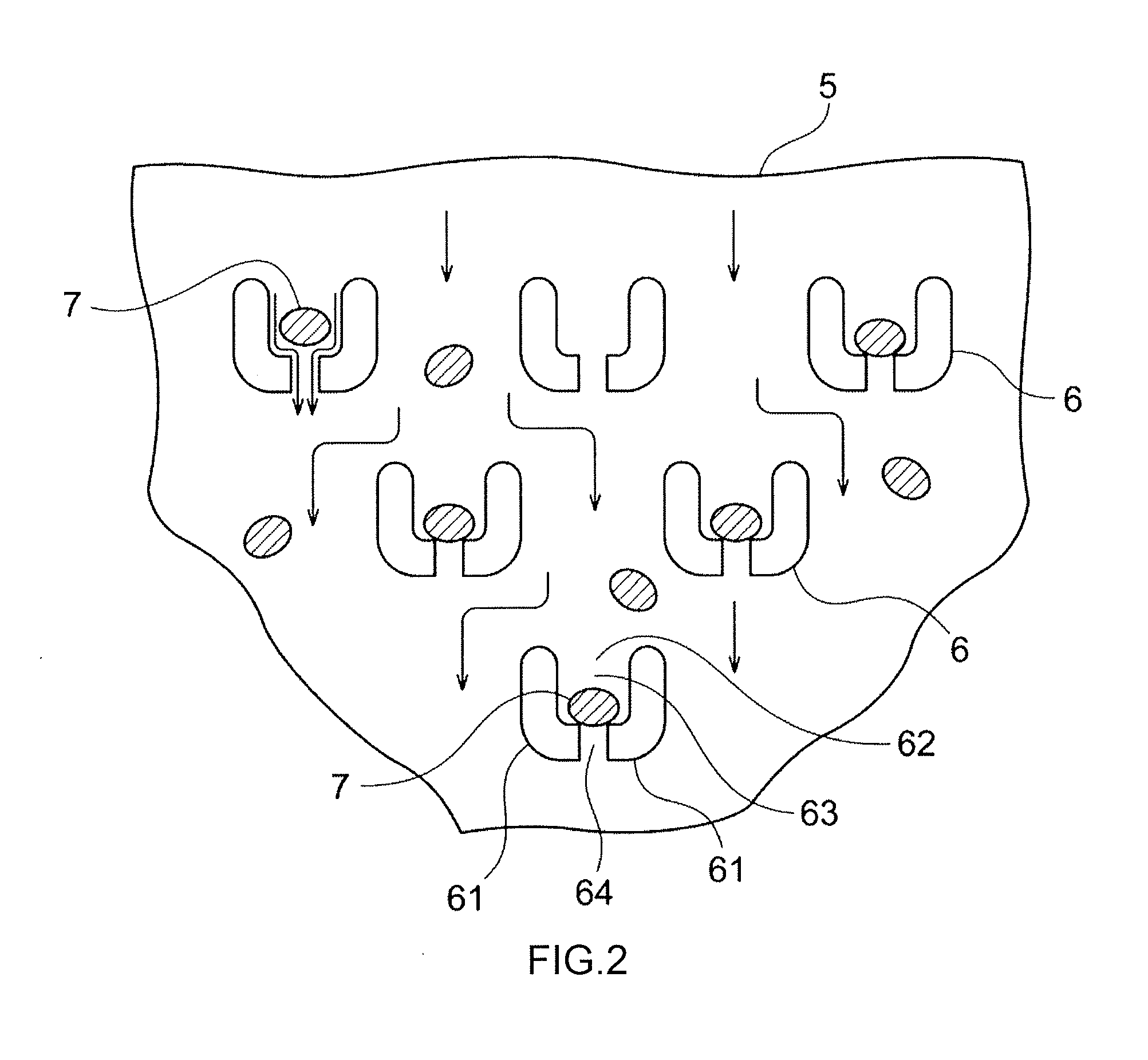
[0090]According to the invention described in claim 1, by just causing a solid-liquid mixture to flow into the passage, solids are carried away by an energized flow of the liquid, only solids having a fixed size or larger are trapped in the midst of the passage, and the liquid and the solids smaller than a predetermined size reach the outlet so that a rate of the obtained liquid with respect to the solid-liquid mixture flown into the passage is high. In this manner, electric field is unnecessary and hence, electrodes and a voltage source become unnecessary whereby the device can be miniaturized, and can be easily manufactured at a low cost. Further, the separation of solids from a liquid can be performed in a short time.
[0091]A width of the region of the separation portion where the solid trapping portions are formed is narrow on a downstream side compared to on an upstream side and hence, a larger number of solids can be trapped in the upstream portion having a large width and the solid-liquid mixture which contains the reduced number of solids is separated on the downstream side whereby a large amount of liquid can be collected even when the width of the region of the separation portion where the solid trapping portions are formed is set narrow on the downstream side compared to the upstream side. On the other hand, in a conventional separation device where a region in which solid trapping portions are formed has a uniform width from an upstream side to a downstream side, when solids are trapped in an upstream portion having a narrow width compared to the upper portion of the present invention, a solid-liquid mixture which subsequently flows is liable to cause clogging so that the flow of a liquid toward the downstream side is decreased.
[0092]Accordingly, the solid-liquid separation device according to the present invention can separate the solid-liquid mixture with high area efficiency and also with a high liquid collection efficiency compared to the conventional solid-liquid separation device. Further, in the conventional solid-liquid separation device where the region of the separation portion in which the solid trapping portions are formed has a uniform width, for example, a converging portion 56 shown in FIG. 7 of patent document 1 is necessary for collecting liquid after separation into one outlet. According to the present invention, a width per se of the region of the separation portion where the solid trapping portions are formed is gradually narrowed toward a downstream side and hence, the separation portion has the above-mentioned liquid converging function whereby it is unnecessary to form the converging portion on the separation portion. Accordingly, the device becomes more compact so that an amount of wasteful liquid which adheres to and remains in the device after separation becomes smaller thus enhancing the liquid collection efficiency.
[0093]The invention descried in claim 2 acquires the substantially same advantageous effects as the invention described in claim 1. Particularly, when the partition wall is formed of the row of columnar bodies, a large number of opening portions are formed in the solid trapping portion and hence, the possibility that all opening portions are closed off by solids having a fixed size or larger is decreased whereby the separation of the solid-liquid mixture can be performed more easily.
[0094]The inventions descried in claims 3 to 6 acquire an advantageous effect that even when the gap becomes smaller than a predetermined gap due to an error in size during or after an assembling of the device, a possibility that distal ends of the row of columnar bodies or the wall body, for example, which constitutes the partition wall are brought into contact with and broken by a face of a counterpart object becomes low, and the distal ends are more easily brought into close contact with the opposedly facing face.
[0095]The invention descried in claim 4 also acquires an advantageous effect that when the partition wall structure is prepared by a stamping method, an operation of removing the partition wall structure from a mold can be performed smoothly with a high yield.

Problems solved by technology

However, it is difficult to simply install a filter in a micrometer-sized flow passage.
For example, mounting of a non-woven fabric or the like as a filter in a flow passage without causing leakage of liquid is difficult because of a miniature size of the flow passage.
Further, the μ-TAS has a drawback that its manufacturing cost is pushed up.
Still further, the μ-TAS has a drawback that an entry portion of a filter portion is likely to be clogged with blood corpuscles thus deteriorating filtering efficiency.

Method used


Image

  • Device having solid-liquid separation function, micro-tas device, and solid-liquid separation method
  • Device having solid-liquid separation function, micro-tas device, and solid-liquid separation method
  • Device having solid-liquid separation function, micro-tas device, and solid-liquid separation method

Examples


Embodiment Construction

[0122]One example of a mode for carrying out the present invention is explained in conjunction with drawings. In this example, a device C having a solid-liquid separation function is, as shown in FIG. 12, used in a state where the device C is incorporated into a μ-TAS (Micro Total Analysis Systems) device body 21. The device C is explained along with one example of a manufacturing method of the device C.

[0123]FIG. 9(a) is a plan view of the μ-TAS device body 21 into which the device C having a solid-liquid separation function is incorporated, and FIG. 9(b) is a cross-sectional view of the μ-TAS device body 21 taken along a line G-G in FIG. 9(a). A cylindrically recessed portion 22 is formed in the μ-TAS device body 21. Assume that an inner diameter of the recessed portion 22 is M and a depth of the recessed portion 22 is N. At least one discharge groove 23 is formed on an inner bottom surface of the recessed portion 22 in a state where the discharge groove 23 extends from a center p...


PUM

PropertyMeasurementUnit
heightaaaaaaaaaa
heightaaaaaaaaaa
sizeaaaaaaaaaa

Abstract

In a device having a solid-liquid separation function, a solid-liquid mixture is introduced through a lid inlet formed in a lid, a separation portion for solid-liquid separation is formed in a groove portion, and solid trapping portions are arranged in the separation portion. Each solid trapping portion is formed of a partition wall and includes an inlet portion, an accommodating portion which accommodates one or more solids that have entered through the inlet portion, and an opening portion which is formed on a downstream side of the accommodating portion and prevents the solid having a fixed size or larger from passing therethrough. A width of a region of the separation portion where the solid trapping portions are formed is narrow on a downstream side compared to on an upstream side.

Description

TECHNICAL FIELD[0001]The present invention relates to a device having a solid-liquid separation function, particularly to a device having a function of filtering out solids having a fixed size or larger from a mixture of liquid and solids, for example, a filtering function having a function of separating blood corpuscles from blood (solid-liquid separation function), a μ-TAS (Micro Total Analysis Systems) device having a filtering function, and a solid-liquid separation method.BACKGROUND ART[0002]Recently, there has been studied and developed a micro chemical device which is called a μ-TAS (μ-Micro Total Analysis Systems) where equipment or a technique used in chemical analysis or synthesis is micronized by making use of a micromachining technique. The μ-TAS has several advantages such as an advantage that just a small amount of specimen is required, an advantage that a reaction time is short and an advantage that the μ-TAS is suitable for analysis. Accordingly, it is expected that ...

Claims


Application Information

Patent Timeline
Patent Type & Authority Applications(United States)
IPC IPC(8): B01D43/00
CPCB01L3/502761B01L2200/0652B01L2200/0668B01L2200/10G01N2001/4088B01L2300/0809B01L2300/087B01L2400/0457G01N33/491B01L2300/0681
Inventor TSUTSUI, HIROSHI
Owner JOSHO GAKUEN EDUCATIONAL FOUND
Why Eureka
Try Eureka