Rotor assembly using polar anisotropic ring magnet

Active Publication Date: 2012-10-18
HEADLINE ELECTRIC
View PDF4 Cites 1 Cited by
  • Summary
  • Abstract
  • Description
  • Claims
  • Application Information

AI Technical Summary

Benefits of technology

[0003]Therefore, a novel rotor assembly is provided so as to obviate the foregoing shortcomings. The rotor assembly contains a number of polar anisotropic ring magnets sequentially stacked, a number of supporting rings within the stacked ring magnets, and an axle threading through the supporting rings. The ring magnets are of a same diameter and length. Each supporting ring contains three co-centric rings: an inner steel ring, a middle rubber ring, and an outer steel ring. The supporting rings are positioned with substantially equal spacing and with a gap away from each aperture of the stacked ring magnets, so that additional weight elements could be positioned and adhered within the gap.
[0004]With the present invention, the manufacturing effort in achieving a true circle for the rotor assembly's outer magnet is reduced. An appropriate number of ring magnets could be utilized and assembled for the motor assembly to build. The periodic positioning of a number of supporting rings could significantly reduce the weight of the motor assembly with much improved steadiness. Additionally, the middle rubber rings of the supporting rings provide a buffer mechanism for absorbing vibration and noise reduction.

Problems solved by technology

During the foregoing manufacturing process, one of the most difficult issues is to achieve true circular inner and outer surfaces of the magnets.
However; this is not an easy task to achieve.
For example, the rubber rings in the terminal pieces are of concern regarding its rotational steadiness and safety, and therefore are not widely applied.
In addition, to achieve the required precision and stability additional fixtures are inevitably and thereby production cost is difficult to reduce.

Method used


Image

  • Rotor assembly using polar anisotropic ring magnet
  • Rotor assembly using polar anisotropic ring magnet
  • Rotor assembly using polar anisotropic ring magnet

Examples


Embodiment Construction

[0013]The following descriptions are exemplary embodiments only, and are not intended to limit the scope, applicability or configuration of the invention in any way. Rather, the following description provides a convenient illustration for implementing exemplary embodiments of the invention. Various changes to the described embodiments may be made in the function and arrangement of the elements described without departing from the scope of the invention as set forth in the appended claims.

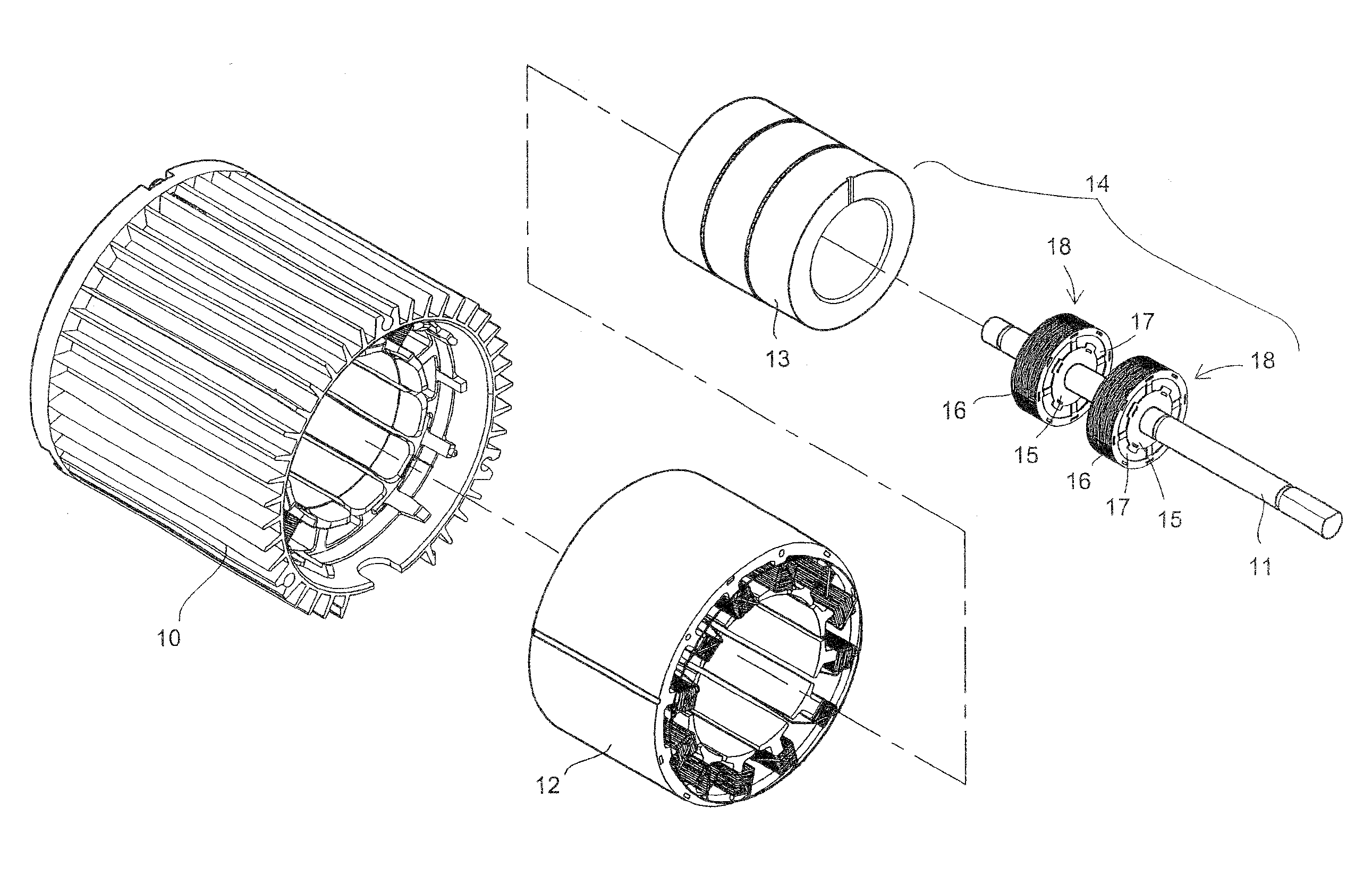
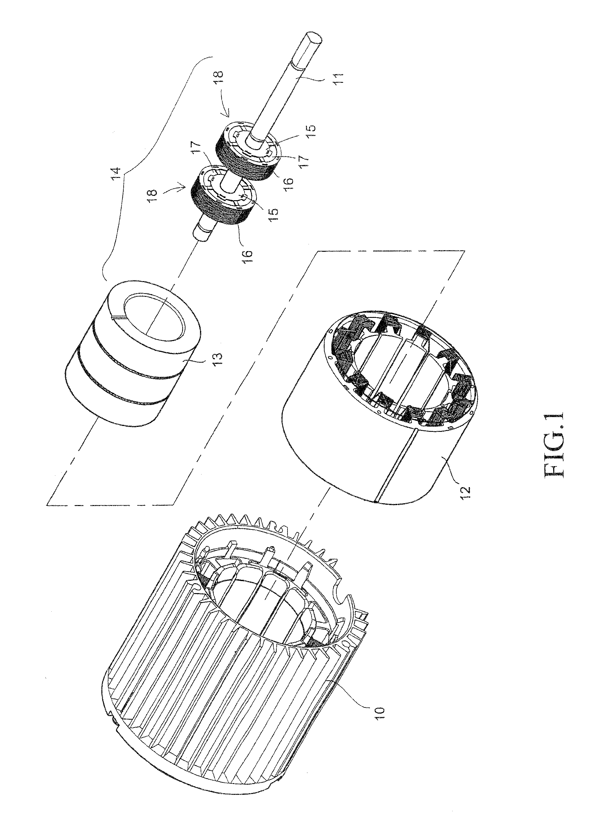
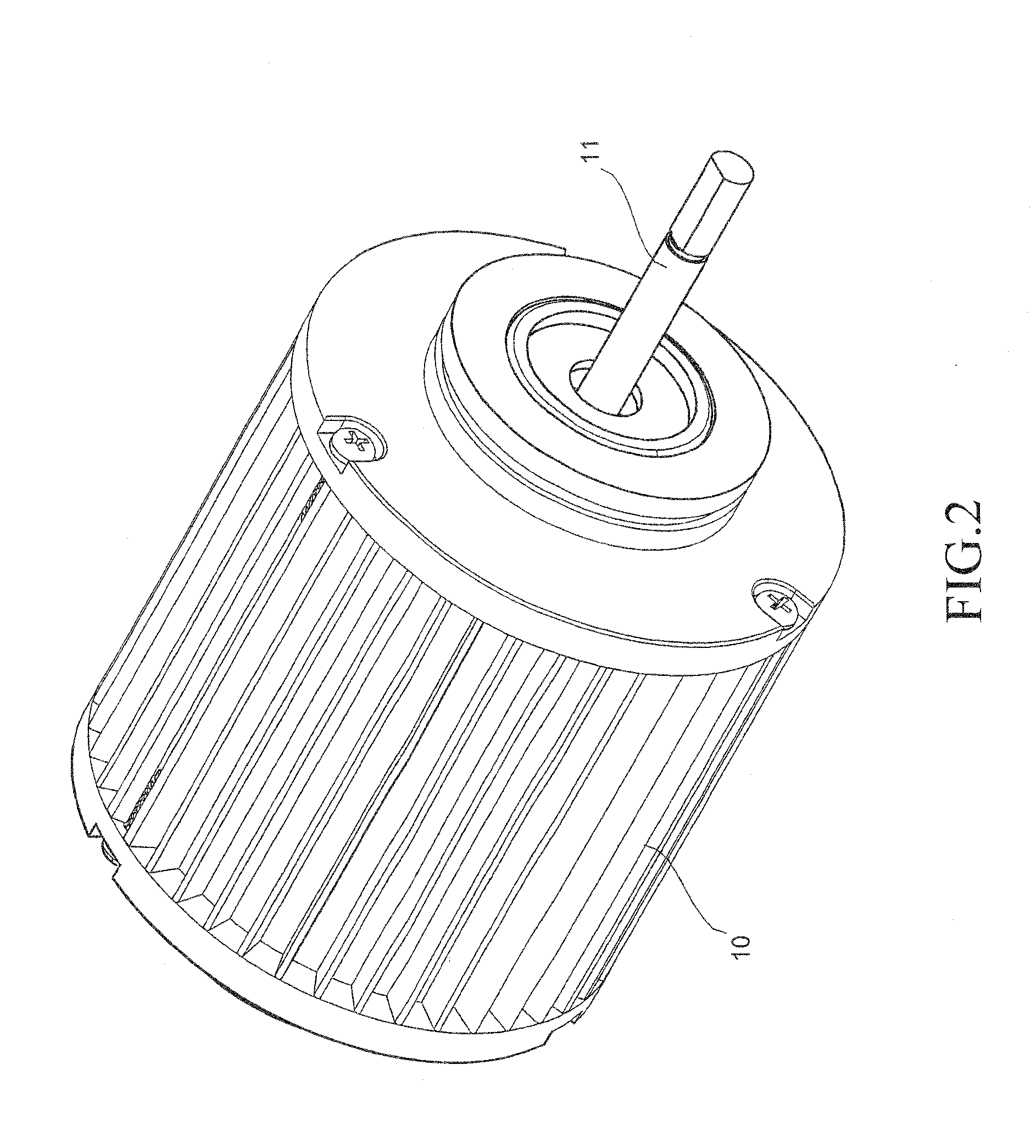
[0014]As shown in FIGS. 1 to 5, a motor assembly according to an embodiment of the present invention contains a main member 10 and an axle 11 extended out of the main member 10, similar to a conventional motor. Within the main member 10, there is a stator 12 and a rotor assembly 14 within the stator 12. The rotor assembly 14 contains a set of polar anisotropic ring magnets 13, a number of supporting rings 18 within the ring magnets 13, and the axle 11 threading through the supporting rings 18. The r...


PUM


Abstract

The rotor assembly contains a number of polar anisotropic ring magnets sequentially stacked, a number of supporting rings within the stacked ring magnets, and an axle threading through the supporting rings. The ring magnets are of a same diameter and length. Each supporting ring contains three co-centric rings: an inner steel ring, a middle rubber ring, and an outer steel ring. The supporting rings are positioned with substantially equal spacing and with a gap away from each aperture of the stacked ring magnets, so that additional weight elements could be positioned and adhered within the gap. The periodic positioning of a number of supporting rings could significantly reduce the weight of the motor assembly with much improved steadiness. Additionally, the middle rubber rings of the supporting rings provide a buffer mechanism for absorbing vibration and noise reduction.

Description

TECHNICAL FIELD OF THE INVENTION[0001]The present invention is generally related to motors, and more particularly to a rotor assembly for motors capable of achieving reduced noise and vibration.DESCRIPTION OF THE PRIOR ART[0002]Conventionally, a number of magnets are tiled along the circumference of a motor's rotor assembly as shown in FIG. 6 and, in order to provide paths for the magnetic flux, some magnetic conducting device is required. In U.S. Pat. No. 6,408,502 and especially for rotors requiring a large diameter, silicon steel plates are stamped into circular ring plates and the ring plates are stacked into a tubular object. The length of the tubular object is dependent on the required length for the rotor. Inside the two end of the tubular object, two terminal pieces having anti-vibration rubber rings are fixedly installed by welding. Then, magnets are tiled around the circumference of the tubular object with the help of appropriate fixtures. During the foregoing manufacturin...

Claims


Application Information

Patent Timeline
IPC IPC(8): H02K5/24H02K1/28
CPCH02K1/2733
Inventor LI, CHIH-YUNGHSU, KUO-SHU
Owner HEADLINE ELECTRIC
Why Eureka
Try Eureka