Condenser microphone unit and condenser microphone

a condenser microphone and microphone technology, applied in the direction of electrical transducers, transducer types, piezoelectric/electrostrictive transducers, etc., can solve the problems of difficulty in obtaining stable acoustic resistance, variation in the width of excised parts, and unavoidable high cost in order to maintain suitable processing accuracy, etc., to achieve good dimensional stability when processing the groove, the effect of arbitrarily setting up the length and width

Inactive Publication Date: 2012-10-18
AUDIO-TECHNICA
View PDF5 Cites 15 Cited by
  • Summary
  • Abstract
  • Description
  • Claims
  • Application Information

AI Technical Summary

Benefits of technology

[0039]That is, according to the above-mentioned etching process (half etching process), the very shallow blind groove having an etched depth of around 5 μm can be formed in the metal fixed electrode with sufficient accuracy, and it is possible to set up its lengths and width arbitrarily.
[0040]Therefore, a lower limit frequency of collecting sounds can be set up appropriately. Further, since dimensional stability when processing the groove is good, it is possible to provide stable acoustic resistance, to thereby prevent variations in the limit frequency of collecting sounds.

Problems solved by technology

Each of these needs a micro fabrication in order to obtain a high impedance, and high cost is unavoidable in order to maintain suitable processing accuracy.
According to the microphone unit 1 shown in FIGS. 10 to 12, since the excised part 5a is formed at the spacer 5 so as to be C-shaped, there is a problem in that the spacer 5 tends to be easily transformed when assembled, leading to variations in width of the excised part 5a particularly and to difficulty in obtaining stable acoustic resistance.
According to this, since a thickness of the film-like diaphragm is as thin as around 2 μm, a problem arises in that it is difficult to obtain very high acoustic resistance required for the non-directional condenser microphone in the case of attempting to apply the device disclosed in Japanese Patent Application Publication No.

Method used


Image

  • Condenser microphone unit and condenser microphone
  • Condenser microphone unit and condenser microphone
  • Condenser microphone unit and condenser microphone

Examples


Embodiment Construction

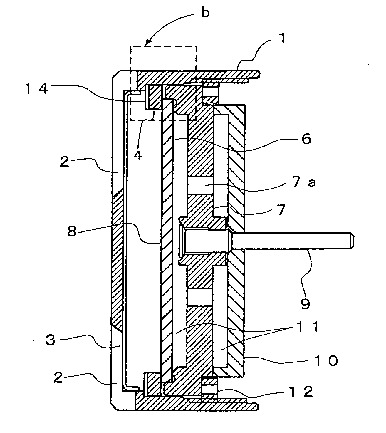
[0053]Hereinafter, a condenser microphone unit and a condenser microphone in accordance with the present invention will be described with reference to a first preferred embodiment shown in FIGS. 1 to 4 and a second preferred embodiment shown in FIGS. 5 and 6. It should be noted that in FIGS. 1 to 6, parts which function similarly to those illustrated in FIGS. 8 and 9 above are denoted by the same reference signs. Accordingly, the description of these parts will not be repeated herein.

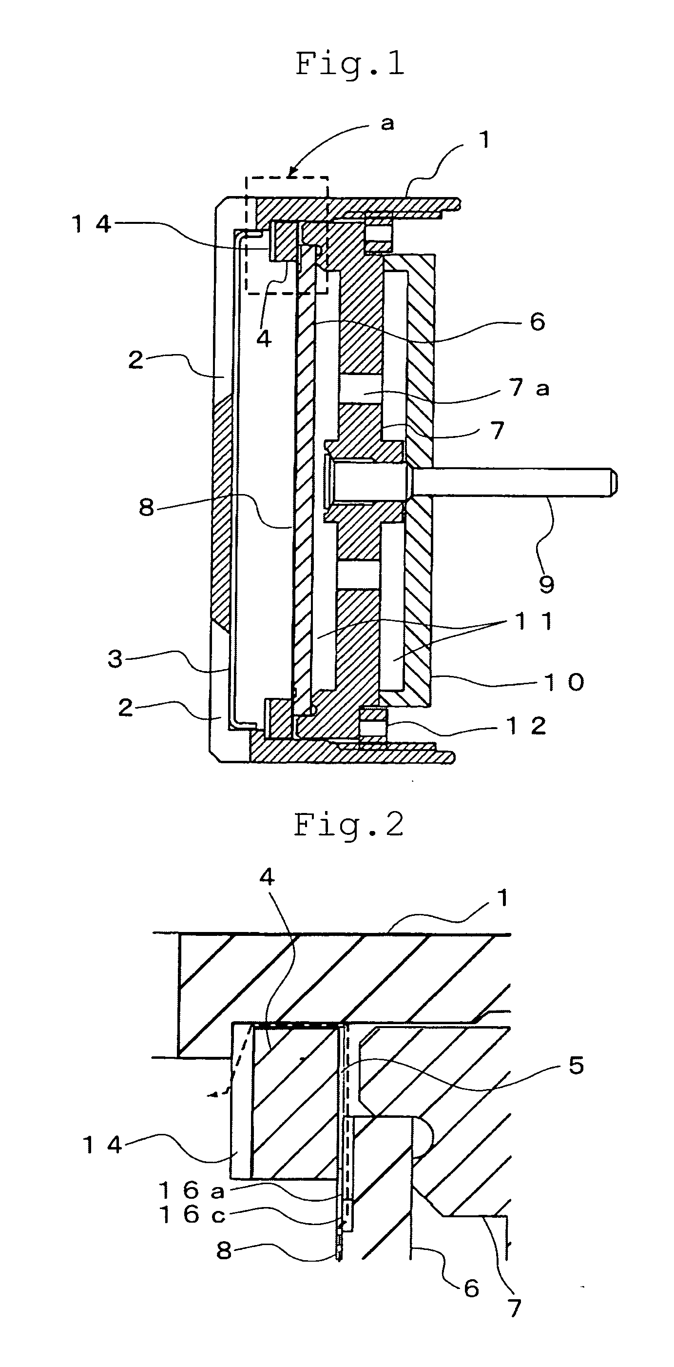
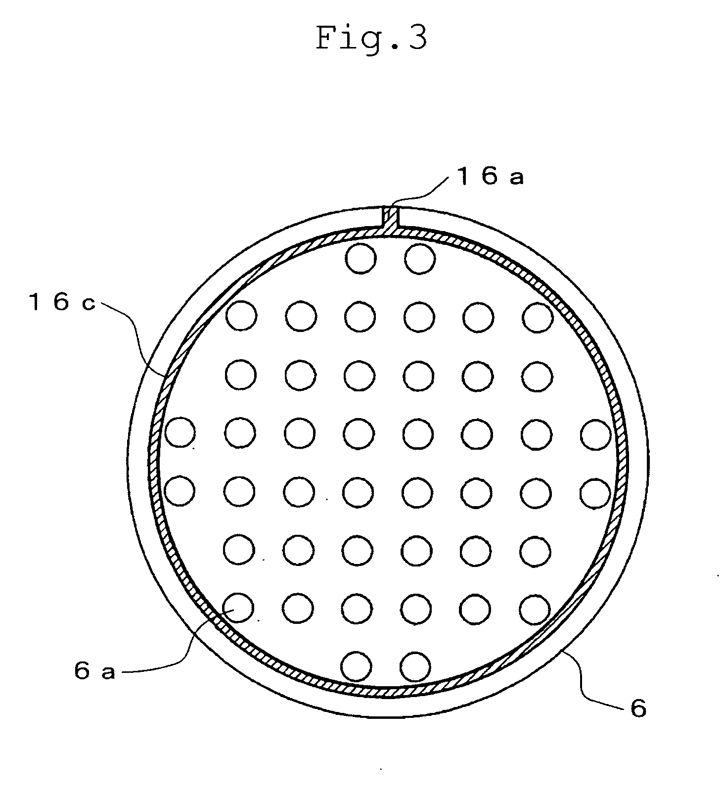
[0054]In the first preferred embodiment of the condenser microphone unit in accordance with the present invention shown in FIGS. 1 to 4, a blind groove is formed by an etching process on one surface of a fixed electrode 6 which is formed in the shape of a disk and made of a metal material, such as for example brass. That is, a blind groove 16a processed by etching is formed in the shape of a straight line at a portion which is in contact with a spacer 5 and in a perimeter edge of the above-mentioned fix...


PUM


Abstract

To stably obtain high acoustic resistance required for pressure equalization in a non-directional condenser microphone unit.
A diaphragm 8 whose circumferential edge is attached to a diaphragm holder 4 and a fixed electrode 6 made of a metal material and arranged to face the diaphragm at a predetermined interval through an electrically insulating spacer 5 are provided, and the rear space of the above-mentioned diaphragm is closed to constitute the non-directional condenser microphone unit. A blind groove 16a is formed by an etching process at a portion which is in contact with the spacer 5 and in the fixed electrode 6 so that the rear space between the diaphragm and the fixed electrode may communicate with the outside, and a communication part formed between the groove 16a and the spacer 5 may be used as acoustic resistance for pressure equalization.

Description

BACKGROUND OF THE INVENTION[0001]1. Field of the Invention[0002]The present invention relates to a non-directional condenser microphone in which a rear space behind a diaphragm is substantially sealed, and to a condenser microphone unit and a condenser microphone provided with a pressure equalizing communication passage which prevents the diaphragm from being displaced with changes in atmospheric pressure, for example.[0003]2. Description of the Related Art[0004]A non-directional condenser microphone is fundamentally such that a rear space behind a diaphragm is sealed and the diaphragm is displaced according to a difference between sound pressure applied to a sound terminal outside (in front of) the diaphragm and pressure in the above-mentioned rear space.[0005]This arrangement provides the non-directional microphone which responses only to loudness of sounds regardless of the direction and angle of the diaphragm in the microphone unit.[0006]FIGS. 8 and 9 show an example of the abov...

Claims


Application Information

Patent Timeline
Patent Type & Authority Applications(United States)
IPC IPC(8): H04R1/02H04R11/04
CPCH04R31/00H04R19/04
Inventor AKINO, HIROSHI
Owner AUDIO-TECHNICA
Why Eureka
Try Eureka