
Method of assembling a jacket structure

a jacket and jacket technology, applied in the field of methods of assembling a jacket structure and a jacket structure, can solve the problems of high welding cost, high welding cost, and associated cos

Inactive Publication Date: 2012-10-18
SIEMENS AG
View PDF14 Cites 16 Cited by
  • Summary
  • Abstract
  • Description
  • Claims
  • Application Information

AI Technical Summary

Benefits of technology

[0009]Joining a node element to a leg or brace by means of an adhesive joint is much faster and less expensive than, for example, forming a welded connection. Furthermore, an adhesive joint is very strong and can withstand high loads applied to it.
[0031]As mentioned above, a jacket structure may easily reach or exceed 50-60 m in height. To be able to access all parts of a leg to which a brace is to be connected, the access means of the jacket assembly guide preferably comprises an elevator. Such an elevator may provide rapid access to all platforms of a supporting tower.

Problems solved by technology

A significant disadvantage of the known method is the associated cost.
For example, welded connections are relatively cost-intensive to complete, since automated welding stations are large and expensive.
Furthermore, the welding procedure is very time-consuming.
Therefore, for an offshore wind park comprising many turbines, the costs of such an assembly procedure can be prohibitive.

Method used


Image

  • Method of assembling a jacket structure
  • Method of assembling a jacket structure
  • Method of assembling a jacket structure

Examples


first embodiment

[0054]FIG. 7 shows various other realizations of node elements for connecting a leg to one or more braces of a jacket structure according to an embodiment. In a first embodiment shown in part A of the diagram, a node 20B is a cast node with two tubular extensions 26 arranged at appropriate angles for connecting to braces. In the example shown, the cast node 20B is connected to the leg parts 101 by means of long bolts 40 through flanges in the interior of the leg. Of course, such a node 20B may be realized with only one tubular extension 26, and two such nodes may be bolted, one above the other, between successive leg parts 101 of a leg.

second embodiment

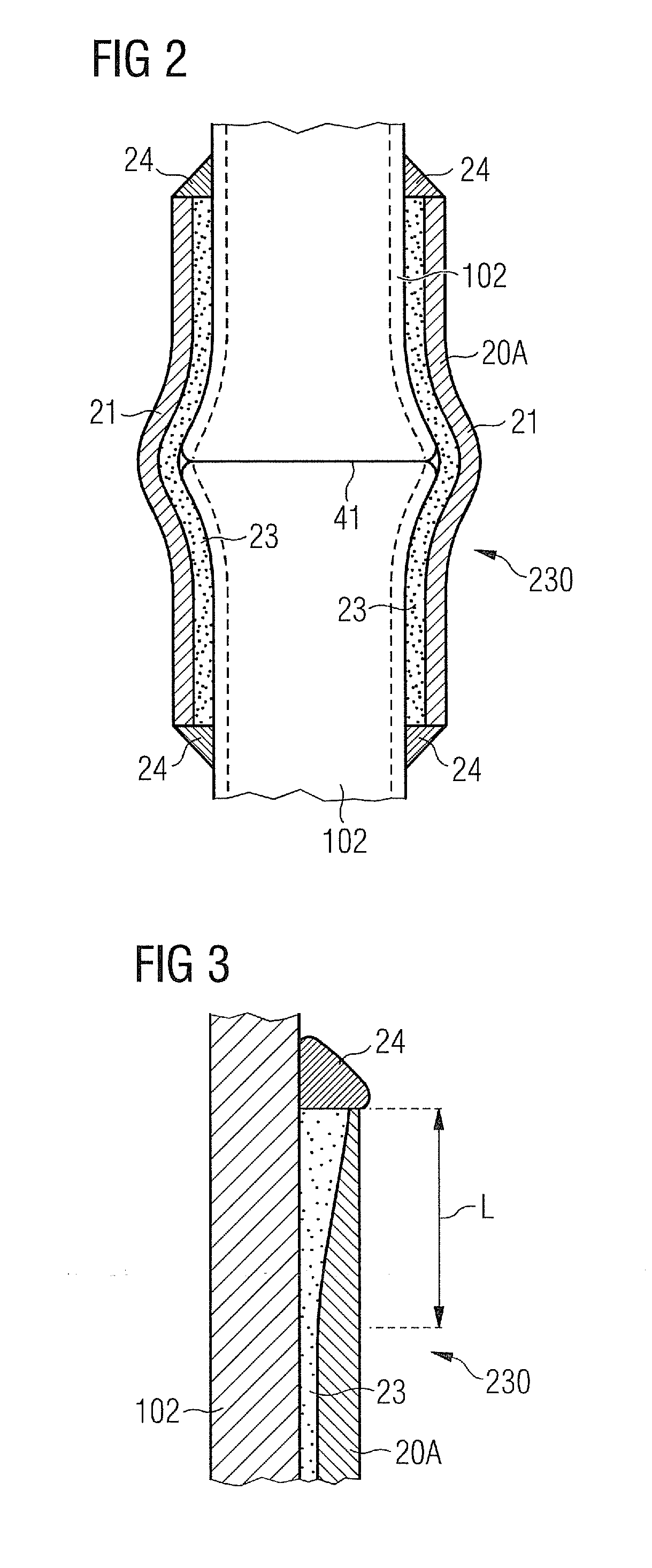
[0055]In a second embodiment shown in part B of the diagram, a node 20C is realized as two halves 21 or shell pieces 21 shaped to fit over a shear key joint 41 or shear lock 41 between leg pieces 102. Instead of a tubular extension, one or more devises 30 may be arranged onto a shell piece 21, for example by casting. Such a clevis 30 comprises a clevis tray 31 and side walls 33 with through holes 32 for connecting to a brace. The node sleeve pieces 21 may be bolted together using short bolts 42 on flanges along the vertical edges of the node sleeve pieces 21.

third embodiment

[0056]In a third embodiment shown in part C of the diagram, a node 20C is realized as two shell pieces 22 shaped to fit over an external flange joint 44 of two leg pieces 103, as indicated by the broken lines. This embodiment might be favorable if leg pieces 103 with external flanges, for bolting together using short bolts, are to be used. The node 20C may be cast with one or more tubular extensions or devises for connecting to a corresponding number of braces.

[0057]A node may connect to more than one brace. For example, for a four-leg jacket, two tubular extensions or clevises may be arranged on a node at essentially right angles to provide connecting points for two braces arranged between two leg pairs, whereby one leg is common to each leg pair, and the node is arranged on that leg. For a three-leg jacket, two extensions may be arranged at an essentially 120° angle to each other on a single node.

[0058]A brace 11 may comprise a pipe piece 110 with a cast gusset 12 at either end (o...


PUM

PropertyMeasurementUnit
Thicknessaaaaaaaaaa

Abstract

A jacket structure for supporting an offshore wind turbine a jacket assembly guide for assembling such a jacket structure and a method of assembling a jacket structure are described The jacket structure includes a plurality of legs, a plurality of connecting braces and a plurality of node elements arranged on the legs for connecting the braces to the legs. A node-to-leg connection is formed between each node element and a leg; and forming a brace-to-node connection between each brace and a node element. A node-to-leg connection and / or a brace-to-node connection include an adhesive joint.

Description

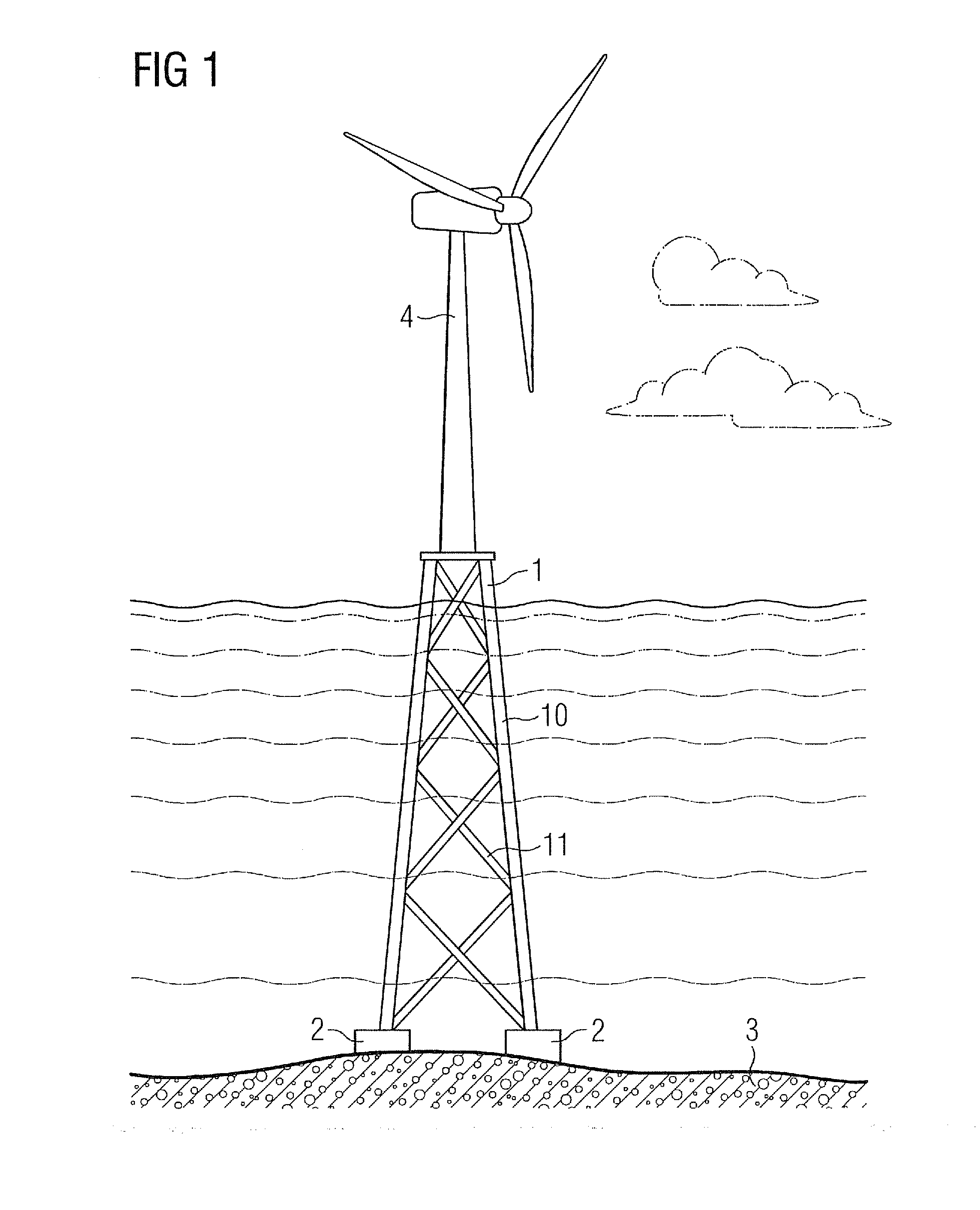
CROSS REFERENCE TO RELATED APPLICATIONS[0001]This application claims priority of European Patent Office application No. 11162605.7 EP filed Apr. 15, 2011. All of the applications are incorporated by reference herein in their entirety.FIELD OF INVENTION[0002]The invention describes a method of assembling a jacket structure, a jacket structure, and a jacket assembly guide.BACKGROUND OF INVENTION[0003]A wind turbine for an offshore wind park must be mounted securely to withstand the forces exerted on it by water and wind. In shallow offshore locations, the wind turbine tower may be mounted on a concrete plinth or foundation that extends into the sea bed. However, for other offshore locations, such mounting techniques may be unsuitable for various reasons. Usually, a “jacket structure” made of three or four upright steel legs is used to support the wind turbine tower in such offshore locations. The upright legs are interconnected by a mesh of braces in the manner of a pylon. The relativ...

Claims


Application Information

Patent Timeline
IPC IPC(8): E02D5/00B23P11/00E02D27/42
CPCE02B17/00E02B17/0004E02B2017/0091Y10T29/49826E04H12/34Y02E10/728E04H2012/006E04H12/10Y02E10/727
Inventor OESTERGAARD, THOMASSTIESDAL, HENRIK
Owner SIEMENS AG
Learn More