

Shielded connector
a shielded connector and connector technology, applied in the direction of connection, electrical apparatus, coupling device connection, etc., can solve the problems of increasing the sensitivity of the connector to external noise in those higher frequencies, and often requiring additional power
- Summary
- Abstract
- Description
- Claims
- Application Information
AI Technical Summary
Benefits of technology
Problems solved by technology
Method used
Image

Examples
Embodiment Construction
[0019]The detailed description that follows describes exemplary embodiments and is not intended to be limited to the expressly disclosed combination(s). Therefore, unless otherwise noted, features disclosed herein may be combined together to form additional combinations that were not otherwise shown for purposes of brevity.
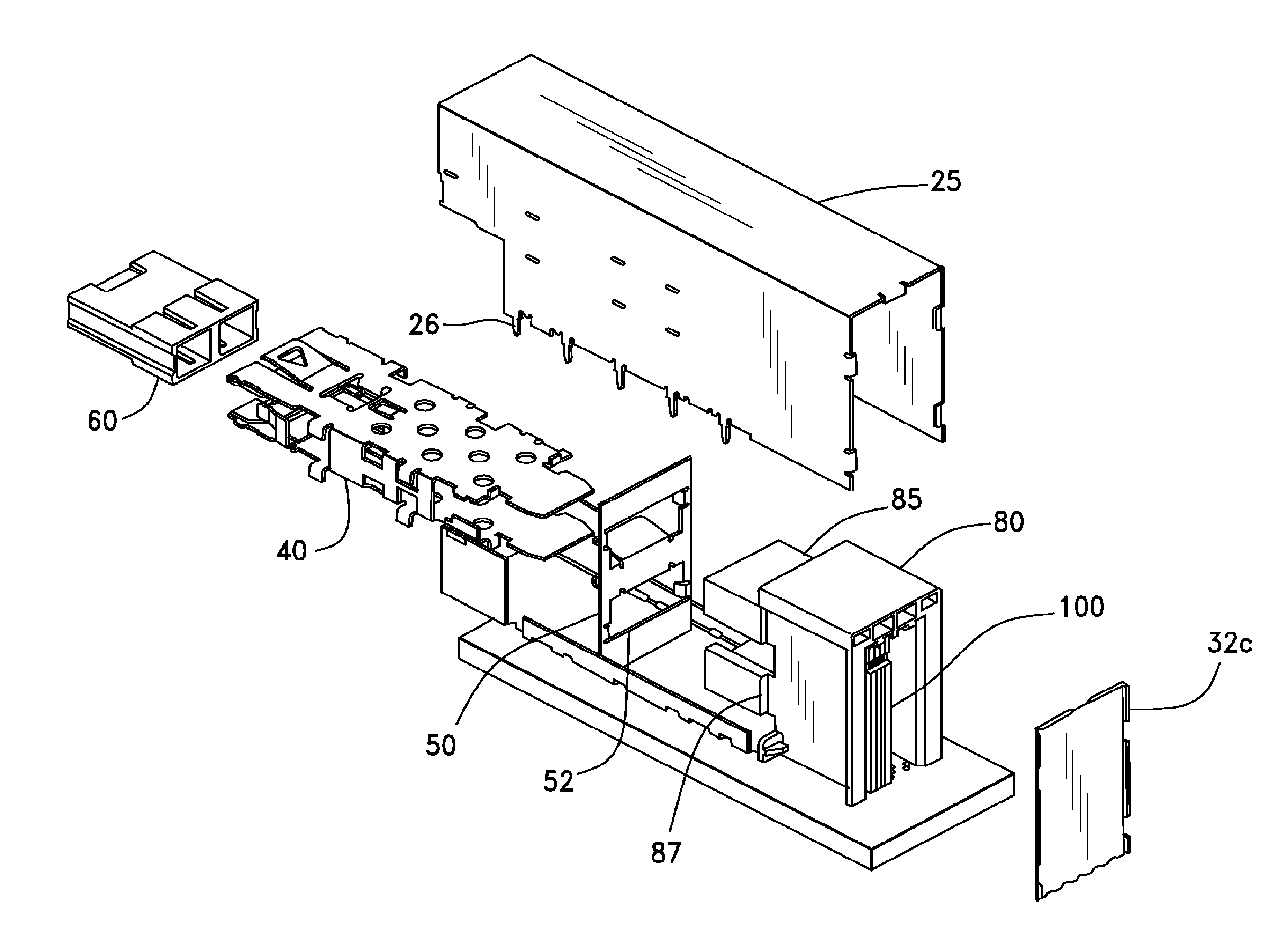
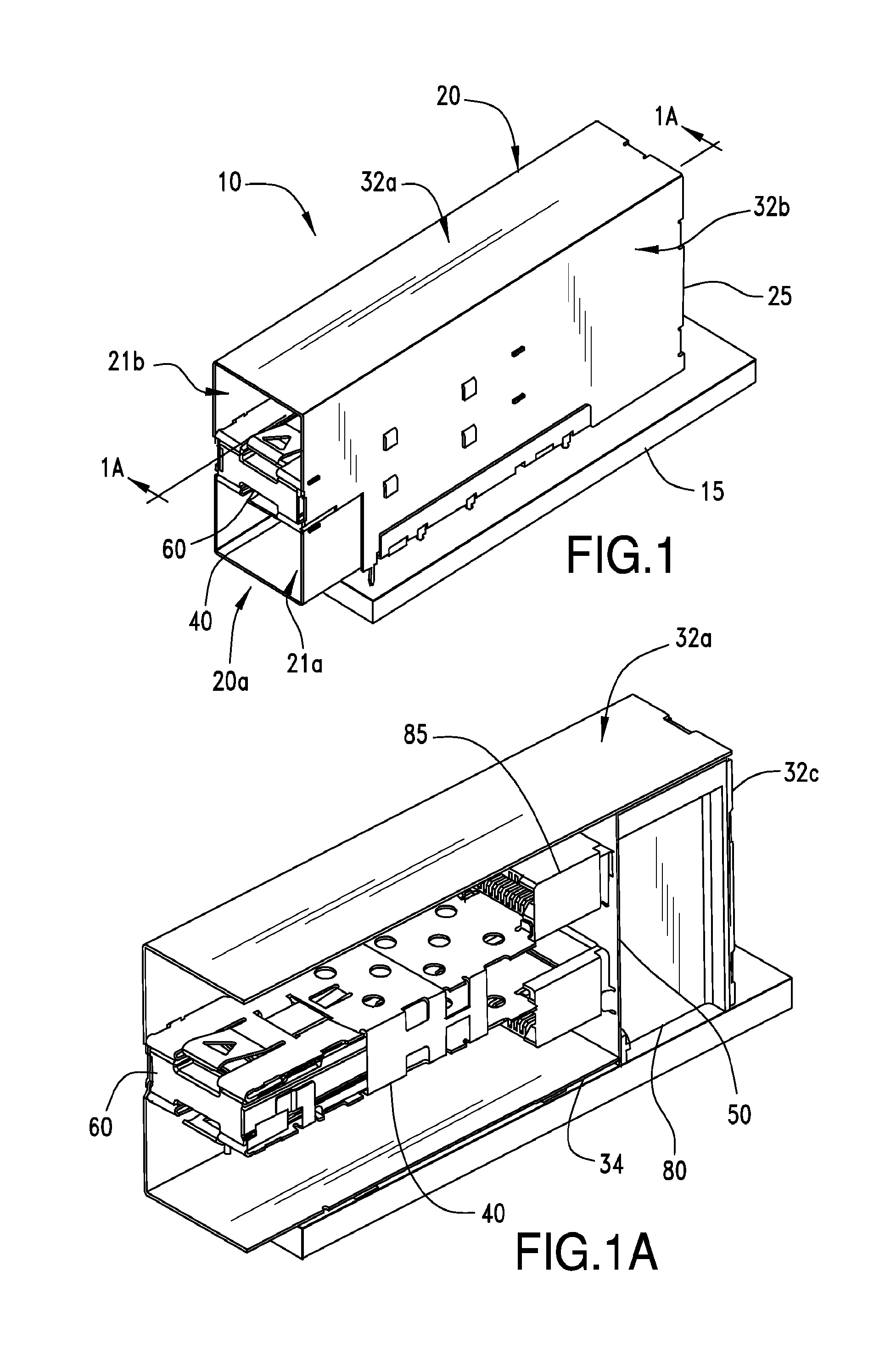
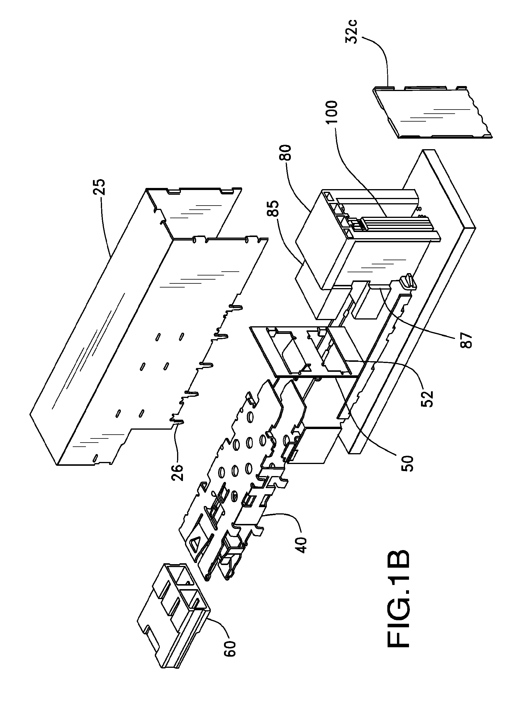
[0020]FIGS. 1-8 illustrate various features that may be incorporated into a connector 10 that is mounted on a printed circuit board (PCB) 15. As can be appreciated, the connector 10 includes a cage 20 that includes a cover 25, a bottom plate 34 and a u-brace 40 that helps define a first port 21a and a second port 21b. The connector 10 thus depicts a stacked connector configuration.
[0021]As can be appreciated, one issue that exists in such designs is the desire to shield from external signals and noise while minimizing the emission of EMI from the connector 10. To help improve the ability of the cage 20 to isolate and act as a shield, a vertical wall 50 is position...
PUM
 Abstract
Description
Claims
Application Information