Method for producing a catalyst slurry blend

a catalyst slurry and blend technology, applied in chemical/physical processes, chemical apparatus and processes, etc., can solve the problems of long transition period, unsuitable for further use production of transition materials, and disturbances of the steady state regime of polymerization reactors, so as to reduce the amount of transition products produced, reduce the loss of production time, and maintain the effect of mixing between blends

Inactive Publication Date: 2012-10-18
TOTAL RES & TECH FELUY
View PDF2 Cites 0 Cited by
  • Summary
  • Abstract
  • Description
  • Claims
  • Application Information

AI Technical Summary

Benefits of technology

[0022]The above provided method allows the preparation of a catalyst slurry blend in an efficient, hence economical way. Time required for the preparation of a new blend and transitioning between blends may be kept minimal. The method allows transitioning from one type of catalyst to another in the production of ethylene multimodal polyethylene products having different properties and characteristics as obtained using another catalyst system to be produced using the same equipment.
[0023]Optimization of the catalyst feed to an ethylene polymerization reactor allows the down-time of the reactor and transition time to another catalyst blend to be kept to a minimum. This is advantageous for reducing the loss of production time and reducing the amount of transition product produced. As the transition product is waste material, it is of economical interest to keep it to a minimum, even to avoid it.

Problems solved by technology

Inadequate catalyst replacements may result in disturbances of a polymerization reactor's steady state regime, long transition periods, production of transition material unsuitable for further use, for instance in an application.

Method used


Image

  • Method for producing a catalyst slurry blend
  • Method for producing a catalyst slurry blend
  • Method for producing a catalyst slurry blend

Examples


example 1

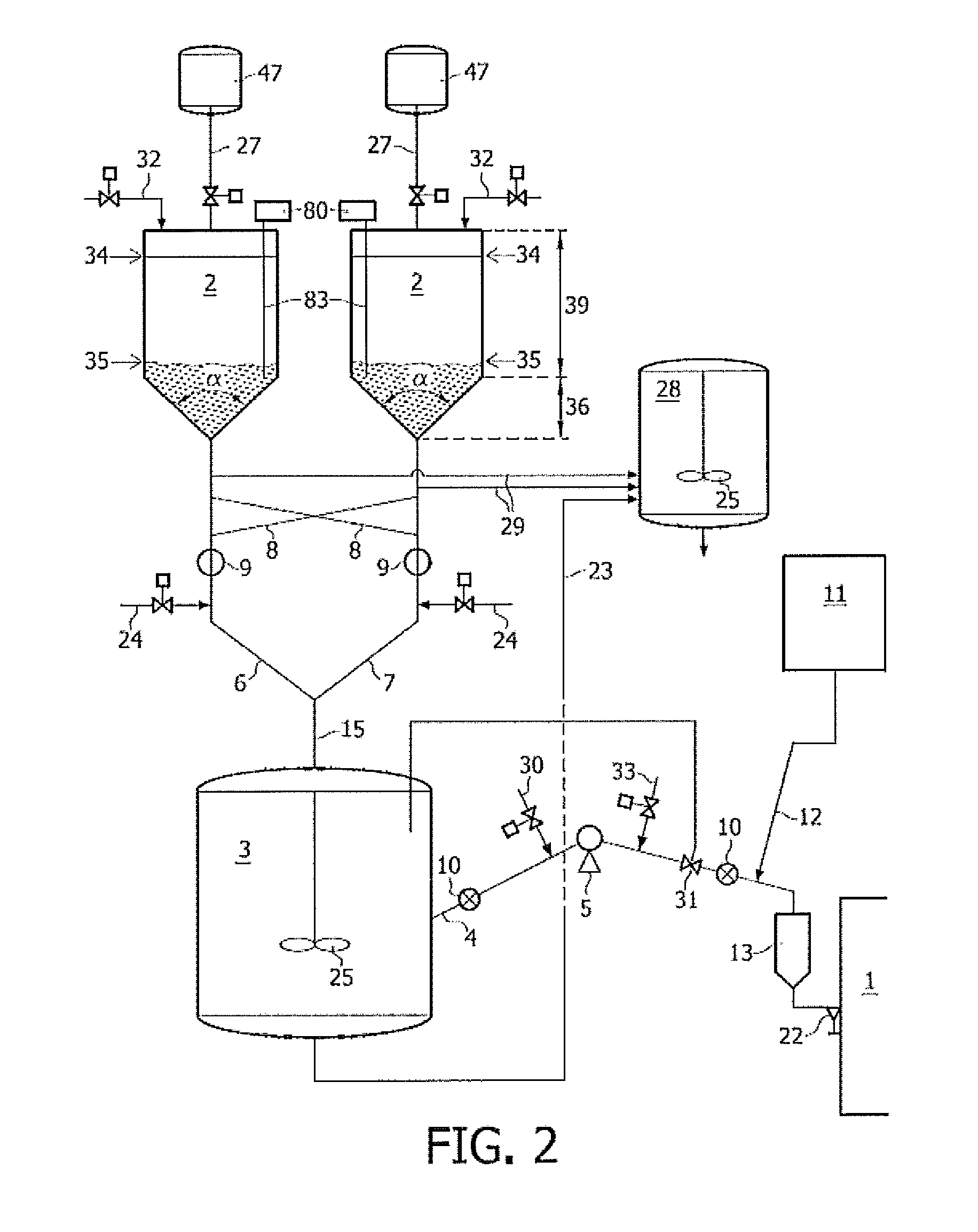
[0098]This example describes the preparation of a catalyst slurry blend of metallocene catalysts and feeding this blend to an ethylene polymerization reactor for the production of a multi-modal polyethylene. The method will be described using a device as illustrated by FIG. 2.

[0099]A metallocene catalyst is solid and is generally provided under a dry form in commercially available packaging. Depending on the diluent used, it may be required to bring the catalyst under higher pressure conditions in the container 47. This is for instance the case when isobutane is used, since this diluent is only liquid at higher pressure levels.

[0100]Preferably pressurizeable catalyst supply containers are used. Pressurizeable containers may be suitable for direct use and coupling to an inlet provided on the mud pot. Use of a larger size pressurizeable container for transportation and supply is therefore preferred. The pressurizeable catalyst supply vessel 47 is preferably suitable for handling press...

example 2

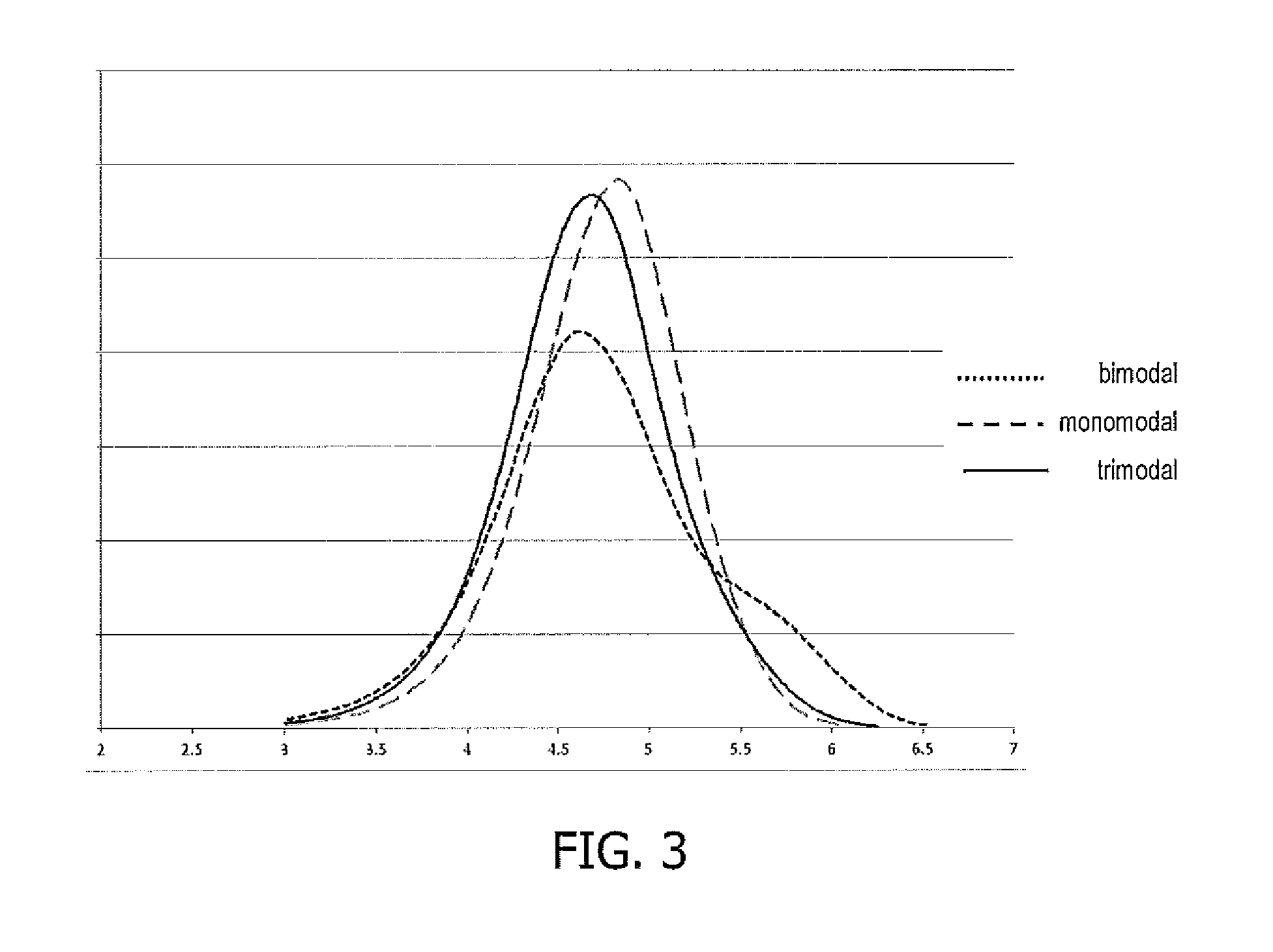
[0128]A blend of 2 different catalysts was prepared as follow: A first ethylene polymerization catalyst (CATA A) was transferred at a first mass flow rate of 3.5 g / h to a mixing vessel, simultaneously a second ethylene polymerization catalyst (CATA B) different from the first one was transferred at a second mass flow rate of 6.5 g / h to said mixing vessel. The flow rates were monitored thereby obtaining a catalyst slurry blend at a concentration suitable for polymerizing ethylene. The activity of each catalyst was 5000 g / g. The catalyst slurry blend then fed to a polymerization double loop reactor, comprising a polymerization slurry of ethylene monomer, comonomer, and diluent. The productivity of the reaction was 50 kg / h of polyethylene, and a trimodal polyethylene was produced. For, comparison a monomodal polyethylene was produced separately using only catalyst A. A Bimodal polyethylene was produced separately using only catalyst B.

[0129]The characteristics of the trimodal polyethyl...


PUM

PropertyMeasurementUnit
angle of reposeaaaaaaaaaa

Abstract

The present invention relates to a method for producing a catalyst slurry blend suitable for polymerizing ethylene in an ethylene polymerization loop reactor for obtaining an at least trimodal polyethylene product, comprising the steps of:
    • transferring a first ethylene polymerization catalyst at a first mass flow rate to a mixing vessel,
    • simultaneously transferring a second ethylene polymerization catalyst at a second mass flow rate to said mixing vessel, thereby in situ providing a catalyst slurry blend, wherein said second ethylene polymerization catalyst is different from the first ethylene polymerization catalyst,
    • adjusting and monitoring said first and second mass flow rates, thereby obtaining said catalyst slurry blend at a concentration suitable for polymerizing ethylene, and
    • feeding said catalyst slurry blend to an ethylene polymerization double loop reactor producing said at least trimodal polyethylene product.

Description

FIELD OF THE INVENTION[0001]The present invention relates to a method for preparing a blend of catalysts in the form of slurry for feeding a polymerization reactor. This invention can advantageously be used in chemical manufacturing, specifically in the production of polyethylene.BACKGROUND OF THE INVENTION[0002]Polyethylene (PE) is synthesized by polymerizing ethylene (CH2═CH2) monomers. Because it is cheap, safe, stable to most environments and easy to be processed polyethylene polymers are useful in many applications. According to the properties polyethylene can be classified into several types, such as but not limited to LDPE (Low Density Polyethylene), LLDPE (Linear Low Density Polyethylene), and HDPE (High Density Polyethylene). Each type of polyethylene has different properties and characteristics.[0003]Ethylene polymerizations are frequently carried out in a loop reactor using ethylene monomer, liquid diluent and catalyst, optionally one or more co-monomer(s), and hydrogen. ...

Claims


Application Information

Patent Timeline
Patent Type & Authority Applications(United States)
IPC IPC(8): C08F2/01C08F210/02C08F110/02
CPCB01J8/0015B01J8/0035B01J8/228B01J2208/0061B01J2208/00769C08F10/02C08F110/02C08F210/16C08F2/01C08F2500/12C08F2500/03C08F2500/05C08F4/00
Inventor DEWACHTER, DAANSLAWINSKI, MARTINE
Owner TOTAL RES & TECH FELUY
Why Eureka
Try Eureka