System, apparatus, and method of reducing production loss having a counterband

a production loss and counterband technology, applied in the field of textile industry, can solve the problems of reducing the production efficiency of the entire system, counterband absorbance, moisture soaking, etc., and achieve the effects of reducing production losses, reducing production losses, and saving time, money and labor

Inactive Publication Date: 2008-01-10
AMERICAN LINC LLC
View PDF10 Cites 8 Cited by
  • Summary
  • Abstract
  • Description
  • Claims
  • Application Information

AI Technical Summary

Benefits of technology

[0012]In view of the foregoing, embodiments of the present invention advantageously provide a system, apparatus, and methods to substantially reduce production loss for yarn. Embodiments of the present invention also advantageously provide a system, apparatus, and methods of increasing production speed of yarn in a continuous production process. Embodiments of the present invention further advantageously provide a system, apparatus, and methods of reducing production loss in yarn that are readily compatible with existing continuous yarn production processes without the necessity of replacing an entire continuous production process system.
[0013]Still further, embodiments of the present invention advantageously provide a system, apparatus, and method of doing business which allow a yarn manufacturer or other yarn textile product producer to significantly reduce the amount of labor, production shifts, production times, and / or machine wear and tear. Embodiments of the present invention yet further still provide a system, apparatus, and methods of reducing production loss in yarn that includes a counterband that does not absorb moisture from the heated fluid, vapor, or steam that is used for heat setting the yarn.
[0014]More particularly, an embodiment of the present invention advantageously provides a yarn system with a yarn conveyor positioned to receive a bundle of yarn. The system also has a heat setting oven positioned to apply heat to the bundle of yarn. The heat setting oven has an oven entrance and an oven exit. The conveyor carries the bundle of yarn into the heat setting oven through the oven entrance for the bundle of yarn to be heated, and out of the heat setting oven through the oven exit after the yarn is heated. The system also has a counterband traveling in a loop such that the counterband enters the heat setting oven through the oven entrance and exits the heat setting oven through the oven exit. At least a portion of the counterband extends between the oven entrance and the oven exit substantially parallel to and above the conveyor to abuttingly contact the bundle of yarn against the conveyor when the heat setting oven is applying heat to the bundle of yarn passing therethrough. The counterband is formed of a plurality of hydrophobic fibers that are woven in a mesh pattern, and thereby form apertures to enhance flow of a heated vaporous fluid between the fibers. The system also has a yarn cooler positioned downstream from the heat setting oven to cool the bundle of yarn exiting the oven exit, to thereby heat set the heated bundle of yarn. A cooling efficiency of the yarn cooler is increased responsive to the hydrophobic fibers allowing the yarn cooler to cool the bundle of yarn without moisture from the heated vaporous fluid being absorbed by the counterband when the heat setting oven is applying heat to the bundle of yarn.

Problems solved by technology

There are several places and mechanisms by which the yarn can become displaced or snagged, which reduces the production efficiency of the entire system.
Moreover, the previous counterbands absorb moisture associated with the steam, become soaked with moisture almost immediately upon start-up, and stay wet for the duration of the operation.
The cold, wet textile counterband inhibits the ability of the steam to heat the bundle of yarn.
When the heat setting is not uniform, the bundle of yarn is not uniform.
Such defects are highly objectionable.
The previous counterbands were also hot and wet upon exiting the heat setting oven.
Because the heat was retained in the moisture absorbed by previous counterbands, the previous counterbands reduced the efficiency and the ability of the yarn coolers to quickly cool the bundle of yarn.
As a result, more labor, more production shifts, longer production times, and / or more machine wear and tear can be required to achieve desired yarn production results.

Method used


Image

  • System, apparatus, and method of reducing production loss having a counterband
  • System, apparatus, and method of reducing production loss having a counterband
  • System, apparatus, and method of reducing production loss having a counterband

Examples


Embodiment Construction

[0052]The present invention now will be described more fully hereinafter with reference to the accompanying drawings in which illustrated embodiments of the invention are shown. This invention, however, may be embodied in many different forms and should not be construed as limited to the illustrated embodiment set forth herein; rather, these embodiment are provided so that this disclosure will be thorough and complete, and will fully convey the scope of the invention to those skilled in the art. Like numbers refer to like elements throughout.

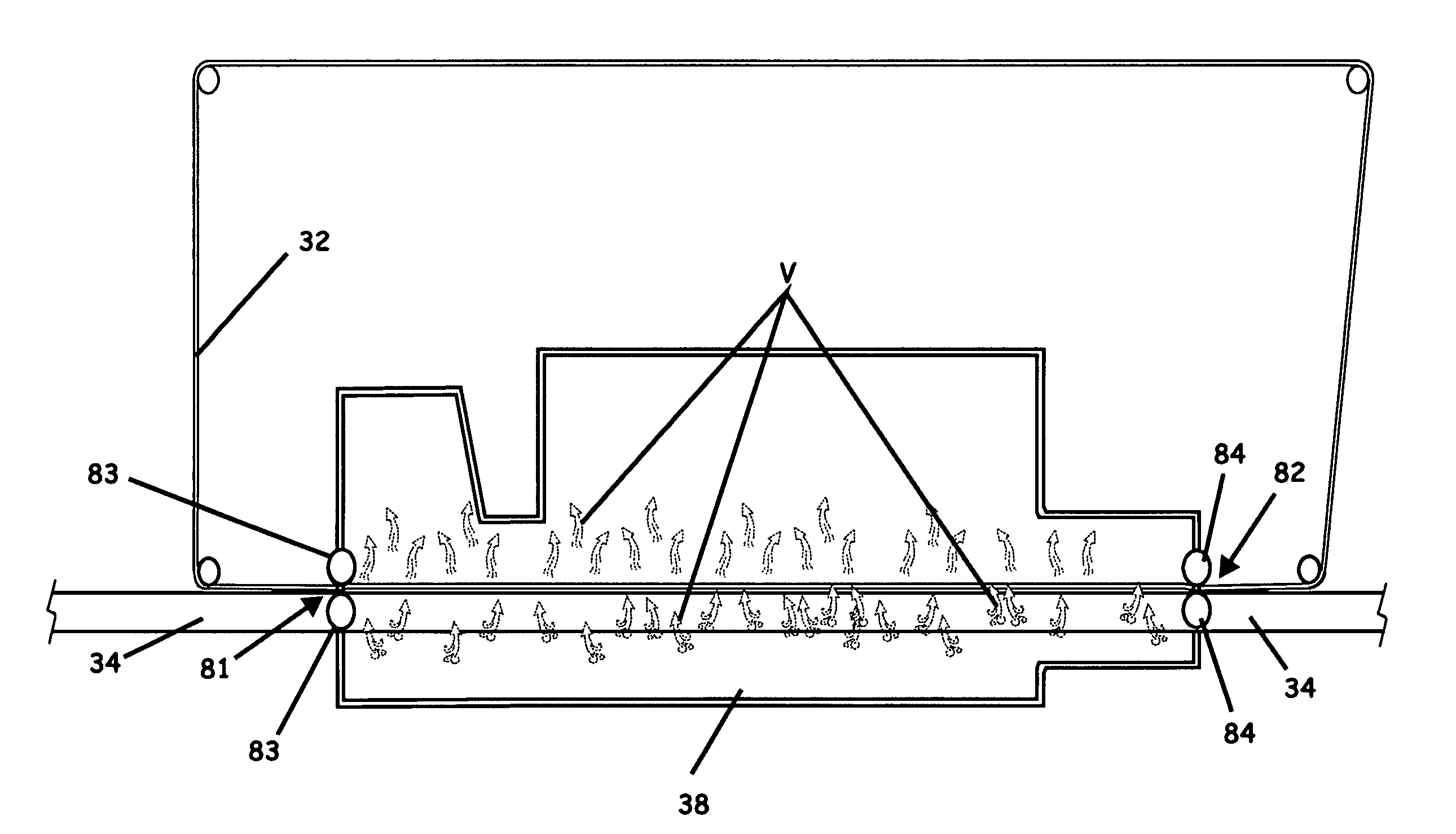
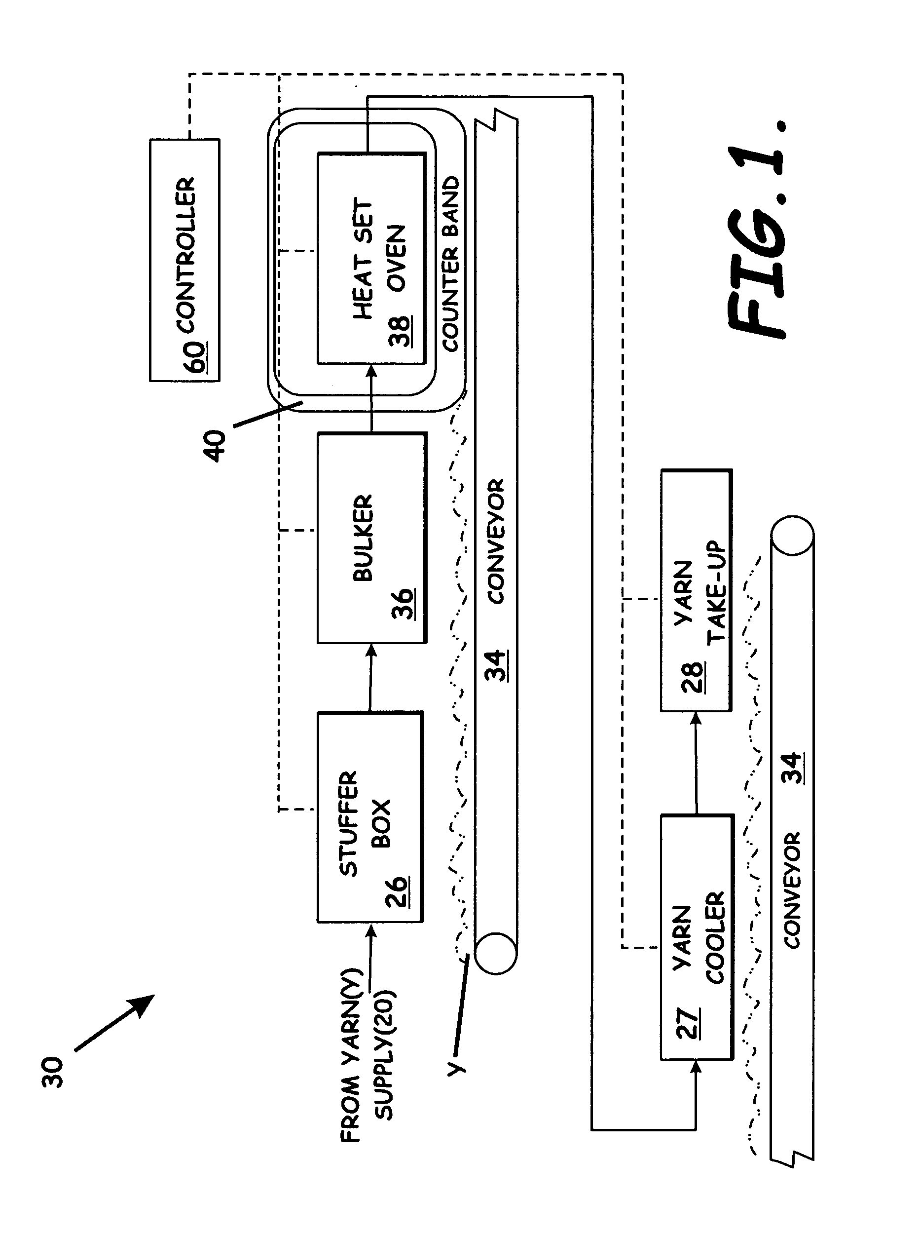
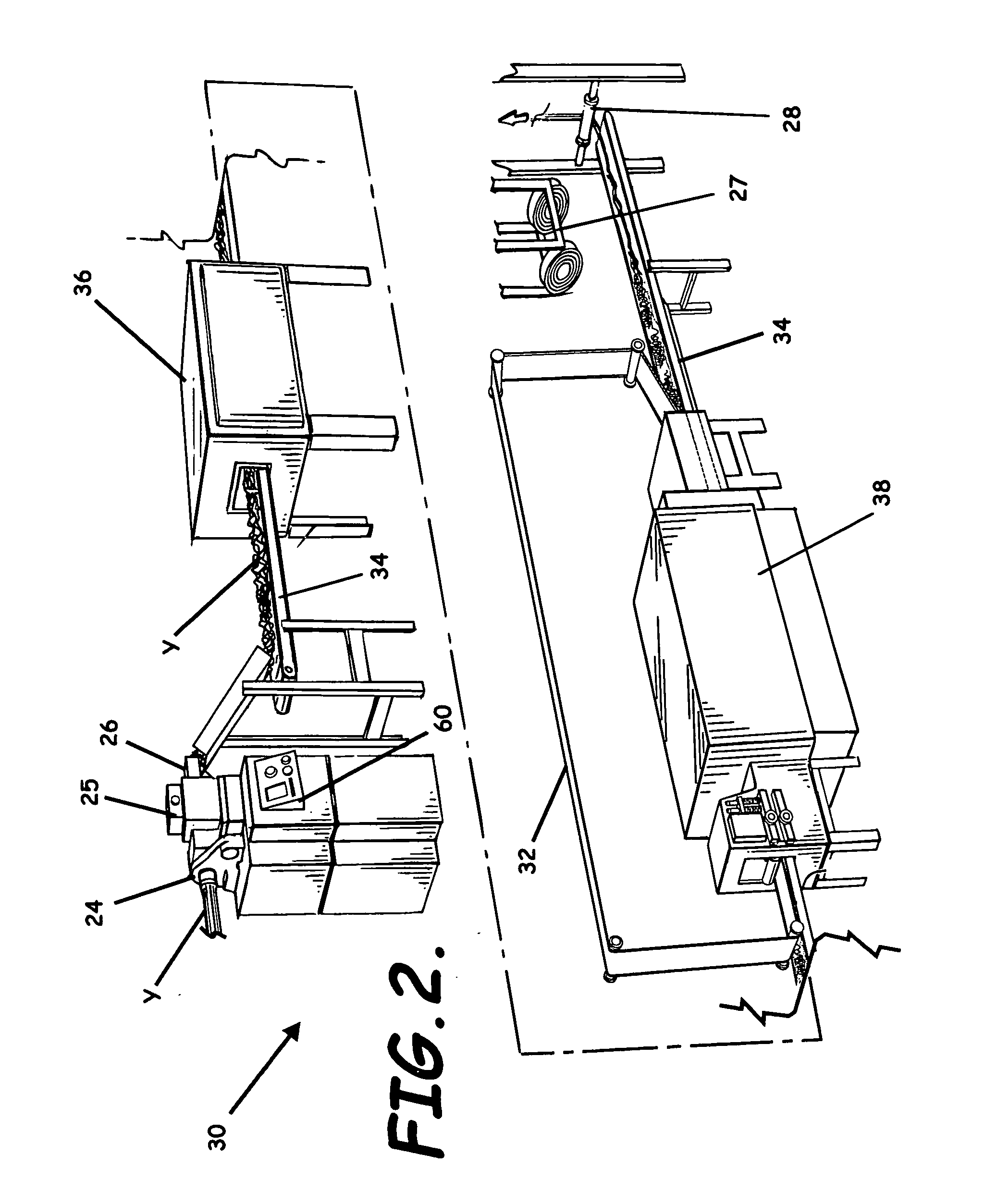
[0053]FIGS. 1-4 illustrate an embodiment of a yarn system 30 to reduce the production loss in yarn Y and, particularly, in a high speed, continuous yarn production process. In one embodiment the system 30 includes a yarn supply 20 or yarn feed having yarn Y, e.g., untexturized yarn or tow, positioned thereon, a yarn guide 22 guidingly receiving a plurality of yarn strands therethrough, a yarn texturizer (e.g., draw rolls 25 and a stuffer box 26)...


PUM

PropertyMeasurementUnit
hydrophobicaaaaaaaaaa
temperatureaaaaaaaaaa
widthaaaaaaaaaa

Abstract

A yarn system, apparatus, and methods of reducing production loss or increasing production speed in a continuous yarn production process are provided. A yarn conveyor receives a bundle of yarn, an oven heats the yarn, and a yarn cooler cools the yarn exiting the oven to heat set the yarn. The conveyor carries the yarn through the oven and cooler. A counterband extends through the oven substantially parallel to and above the conveyor to abuttingly contact the yarn against the conveyor. The counterband is formed by hydrophobic fibers woven in a mesh pattern that form apertures to enhance flow of a heated fluid between the fibers. A cooling efficiency of the cooler is increased responsive to the hydrophobic fibers allowing the cooler to cool the yarn without moisture from the heated fluid being absorbed by the counterband.

Description

BACKGROUND OF THE INVENTION[0001]1. Field of the Invention[0002]The present invention relates to the textile industry and, more particularly, to systems, devices, and methods of producing yarn.[0003]2. Description of Related Art[0004]In the textile industry, various systems have been developed over the years for producing texturized and straight set yarn in a high speed, continuous production process such as for use in carpet related products or other textile products. Many systems often include a yarn supply, a false twister positioned downstream from the yarn supply to impact a false twist to the yarn to enhance cohesiveness, one or more draw rolls positioned downstream from the false twister, a stuffer box or stuffer can to crimp or otherwise form a texture in the yarn, a yarn conveyor belt positioned downstream from the stuffer box and positioned to receive the yarn thereon to convey the yarn downstream, a bulker positioned to receive the yarn conveyor and to initially heat bulk...

Claims


Application Information

Patent Timeline
Patent Type & Authority Applications(United States)
IPC IPC(8): D02G1/20
CPCD02J13/001D02G1/20D02G1/12
Inventor LAIRD, DEBORAH A.KENNEDY, EDWARD J.O'BRYAN, WILLIAM R.
Owner AMERICAN LINC LLC
Why Eureka
Try Eureka